Operator Control and Display Panel
4
2.0 OPERATOR CONTROL AND DISPLAY PANEL
2.1 Operator Control Panel
The control panel and LCD on the front of the NX lets the operator:
• turn the UPS on or off
• transfer into the various operating modes
• silence alarms
• check the status of the UPS and its batteries, including all measured parameters, events and
alarms
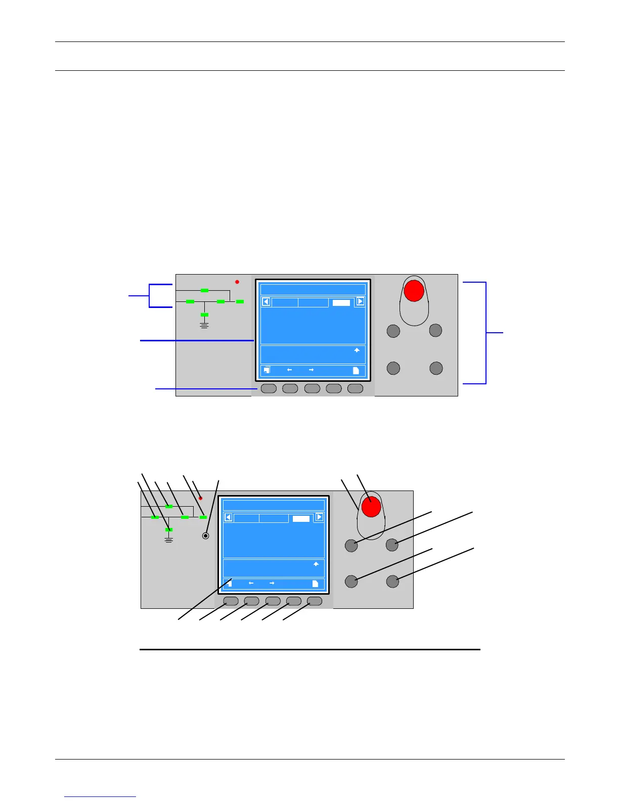
The main areas of the control panel are shown below in Figure 2 and detailed in Figure 3.
• Mimic Display - view the status of the NX in single-line diagram format—indicators show status
by changing color when ON, flashing or OFF
• Liquid Crystal Display (LCD) and Navigation keys - view status and operational data from
the NX in tabular format
• Control buttons - turn the NX on or off, silence alarms
Figure 2 Overview of control panel
2.1.1 Display Panel Layout
Figure 3 shows the control panel in greater detail, identifying individual items that are described in
the rest of this section.
Figure 3 Detailed view of control panel
EPO
INVERTER ON INVERTER OFF
FAULT CLEAR SILENCE ON/OFF
Liebert NXb
2003-01-22 12:30:36
30KVA-3X3
Uni t # 1 Nor m al
?
Bypas s
Main
Vphase V
Iphase A
Fre q. Hz
Vline V
P. F.
A(AB)
120
20.5
50.1
208
0.99
B(BC)
120
20.5
50.1
208
0.99
C(CA)
120
20.5
50.1
208
0.99
F2 F4 HELPF1 F3
Output
Input Breaker Closed 01-12 12:28:16
Manual Turn On 01-12 12:30:06
UPS in Normal Mode 01-22 12:30:16
Mimic display
Navigation keys
Liquid Crystal
Display (LCD)
Control
buttons
Mimic indicators Control buttons Navigation keys
1. Rectifier indicator 8. Button cover 15. F1
2. Battery indicator 9. EPO button 16. F2
3. Bypass indicator 10. INVERTER ON button 17. F3
4. Inverter indicator 11. INVERTER OFF button 18. F4
5. Load indicator 12. FAULT CLEAR button 19. Help
6. Alarm indicator 13. SILENCE ON/OFF button
-------------------------------------
7. Buzzer
---------------------------------------------------
14. LCD
EPO
INVERTER ON INVERTER OFF
FAULT CLEAR SILENCE ON/OFF
Liebert NXb
2003-01-22 12:30:36
30KVA-3X3
Unit #1 No r m al
?
Byp as s
Main
Vphase V
Iphas e A
Fre q . Hz
Vline V
P. F.
A(AB)
120
20.5
50.1
208
0.99
B(BC )
120
20.5
50.1
208
0.99
C(CA)
120
20.5
50.1
208
0.99
F2 F4 HELPF1 F3
Output
Input Breaker Close d 01-12 12:28:16
Manual Turn On 01-12 12:30:06
UPS in Normal Mode 01-22 12:30:16
1
2
3
4
5
6
7
9
10
11
12
13
14
15 16 17 18 19
8

 Loading...


