Operator Control and Display Panel
5
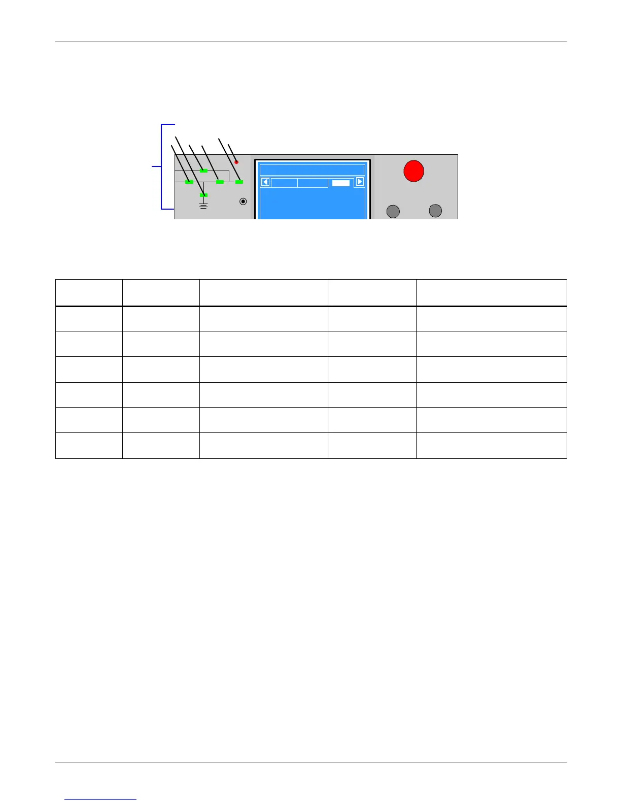
2.2 Mimic Display Indicators
The Mimic display on the front panel consists of six indicators arranged in a single-line diagram
depicting the various paths of UPS power, as shown in Figure 4.
Figure 4 Mimic display indicators location
The current operational status of the NX is indicated by the color of the indicators—green, amber or
red—and whether they are ON (solid), flashing or OFF. Table 1 provides a guide to interpreting the
various states of the indicators.
Table 1 Mimic display status indicators
Indicator
(see Figure 4) Green Flashing Green / Amber Red Off
1. Rectifier Load on rectifier
Flashing Green: Utility normal,
but rectifier not operating
Rectifier fault
Rectifier is normal, but utility is
abnormal
2. Battery
Battery powering
the load
Flashing Green: Battery pre-
warning (low battery)
Battery or battery
converter abnormal*
Battery and converter are normal,
and battery is not discharging
3. Bypass
Load on Bypass
power
—
Bypass out of
normal range
Bypass Normal
4. Inverter
Inverter powering
the load normally
Flashing Green: Inverter on
standby
Inverter fault Inverter normal, but off
5. Load UPS output on —
UPS output
overloaded
UPS no output
6. Alarm
No alarms—UPS
working normally
Amber: UPS has general
alarm
UPS has serious
fault
—
* Battery or battery converter abnormal events include these event messages (see Table 8 in Appendix A): No Battery, Battery Replaced,
Battery Reverse, Batt. Conv. Over. Curr., Batt. Converter Fault, Batt. Converter Overtemp.
Mimic indicators
1. Rectifier indicator
2. Battery indicator
3. Bypass indicator
4. Inverter indicator
5. Load indicator
6. Alarm indicator
EPO
Liebert NXb
2003-01-22 12:30:36
30KVA-3X3
Uni t # 1 Nor m al
Bypas s
Main
Vphase V
Iphase A
Fre q. Hz
Vline V
A(AB)
120
20.5
50.1
208
B(BC)
120
20.5
50.1
208
C(CA)
120
20.5
50.1
208
Output
1
2
3
4
5
6

 Loading...


