Operating Instructions
19
4. Turn the rotary switch to BYPASS.
The maintenance switch SW1-D opens and output switch SW1-A closes. The UPS powers from
static bypass instead of from maintenance bypass. The bypass and load indicators turn on. The
design of the rotary switch ensures uninterrupted output.
5. Turn the rotary switch to NORMAL, then press the INVERTER ON control button for 2 seconds.
The inverter will start and the inverter indicator will flash green. After the inverter is ready, the
UPS transfers from bypass to inverter, the bypass indicator turns off and the inverter and load
indicators turn on.
The UPS is operating normally. The UPS Mimic display indicators will:
3.2.2 Verify Switching Between Operation Modes
Switch from Normal Mode to Battery Mode
• Open CB1 to enter battery mode. This breaks the utility connection to the NX.
To return to normal mode, close CB1 after a few seconds. The rectifier will restart automatically
after 10 seconds and resume feeding power to the inverter.
Switch from Normal Mode to Bypass Mode
• Press INVERTER OFF button to switch to bypass mode.
Switch from Bypass Mode to Normal Mode
• Turn the rotary switch to NORMAL.
• In bypass mode, press the INVERTER ON button. When the rectifier is ready, the UPS will
switch to normal mode.
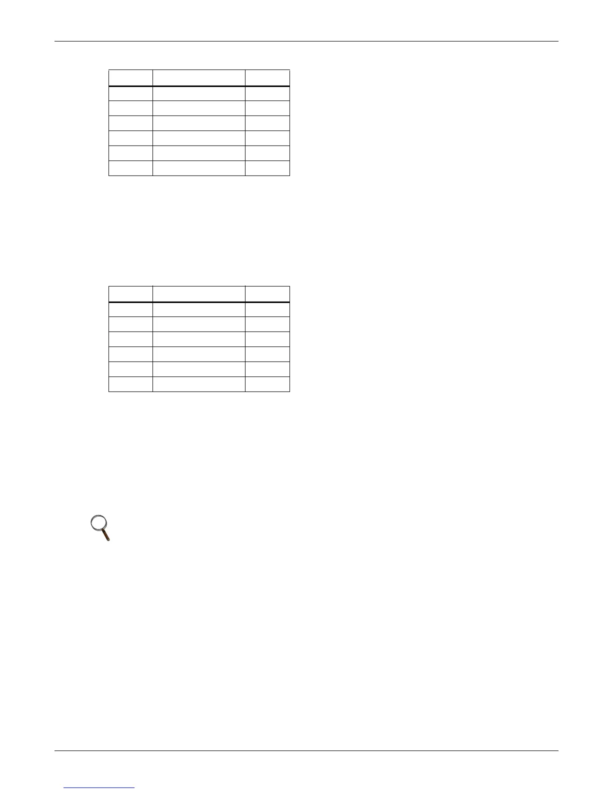
# Indicator State
1 Rectifier indicator Green
2 Battery indicator Off
3 Bypass indicator Green
4 Inverter indicator Off
5 Load indicator Green
6 Alarm indicator Amber
# Indicator State
1 Rectifier indicator Green
2 Battery indicator Off
3 Bypass indicator Off
4 Inverter indicator Green
5 Output indicator Green
6 Alarm indicator Green
NOTE
In bypass mode, the load is being powered by the utility and is not receiving conditioned power
through the rectifier.
 Loading...


