UPS Status Messages
28
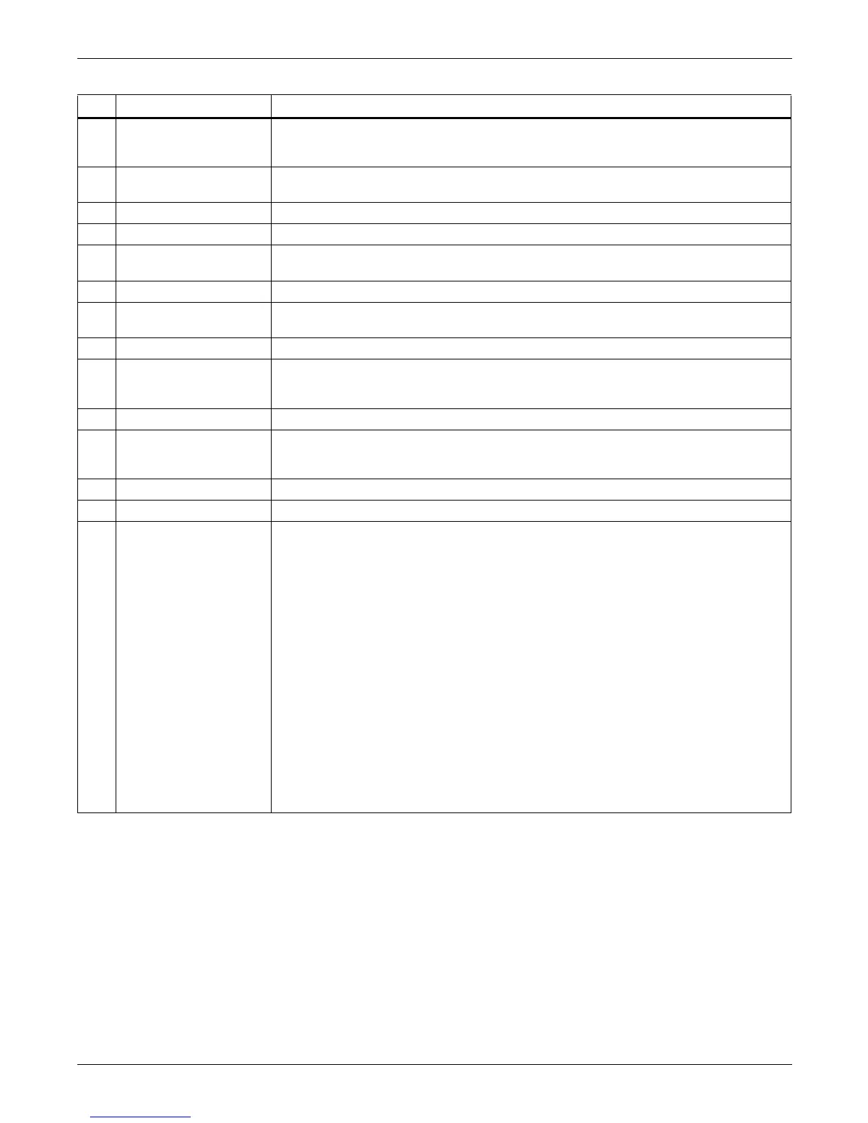
16 Rectifier Overtemp.
The temperature of heat sink is too high to keep the rectifier running.
Suggested Action
The UPS can recover automatically. Check the environment and ventilation.
17 Balancer Fault
The difference voltage between the bus+ and bus- is above 50V.
Balancer: Balance Circuit
18 Balancer Over Current The IGBT current for balance circuit is over 3 times of rated current.
19 Batt. Contactor Fail Battery contactor monitor status is different from drive signal.
20 Batt. Converter Fault
The difference between the output voltage of battery converter and the preset value is over
limit.
21 Batt. Conv. Over. Curr. Battery converter is over current.
22
Batt. Converter
Overtemp.
The temperature of battery converter is over limit
23 Charger Fault The Charger is fault.
24 Input Fuse Fail
Input fuse is broken.
Suggested Action
Replace the input fuse
25 Control Power 1 Fail Control Power 1 is fail or lost.
26 Mains Phase Reversed
Input phase sequence is inverse.
Suggested Action
Check the wiring of rectifier input cables
27 Rectifier Overcurrent The current of Rectifier is over limit.
28 Soft Start Fail Rectifier could not start due to low DC bus voltage
29 Bypass Unable to Trace
This alarm is triggered by an inverter software routine when the amplitude or frequency of
bypass voltage is beyond the normal range.
The amplitude threshold is fixed for positive and negative 10% rating. The frequency
threshold is set via the configuration software (±2 Hz for default).
This alarm automatically resets once the bypass voltage goes normal.
Suggested Action
1. First verify that the bypass voltage and frequency displayed on the panel is within the
selected range. Note here the rated voltage and frequency are specified by “Output
voltage level” and “Output frequency level” respectively. And once this alarm occurs,
there is a hysteresis loop of 5V in phase voltage and 0.1Hz in frequency to recover.
2. If the displayed voltage is believed to be abnormal, then verify the bypass voltage and
frequency presented to the UPS. Check the external supply if it is found to be faulty. If
the utility is likely to trigger this alarm frequently, the alarm can be neglected through
the configuration software according to customer’s requirement. Or the bypass
frequency synchronization range can be changed a little larger through the
configuration software according to the customer’s agreement.
3. If Step 2 shows the displayed bypass voltage and frequency are quite different from the
actual bypass voltage and frequency, measure the signal to the U1 board. If this is
correct then replace the U1 Control Board; else check the wiring connections to M4
measure board, and if this is correct replace the M4 measure board.
Table 8 UPS status messages (continued)
No. Event Message Description / Suggested Action (if any)
 Loading...


