ORPHEUS User’s Manual
Light Conversion support@lightcon.com 15
4. POSITIONING AND CONNECTING ORPHEUS
4.1 System Layout on Optical Table
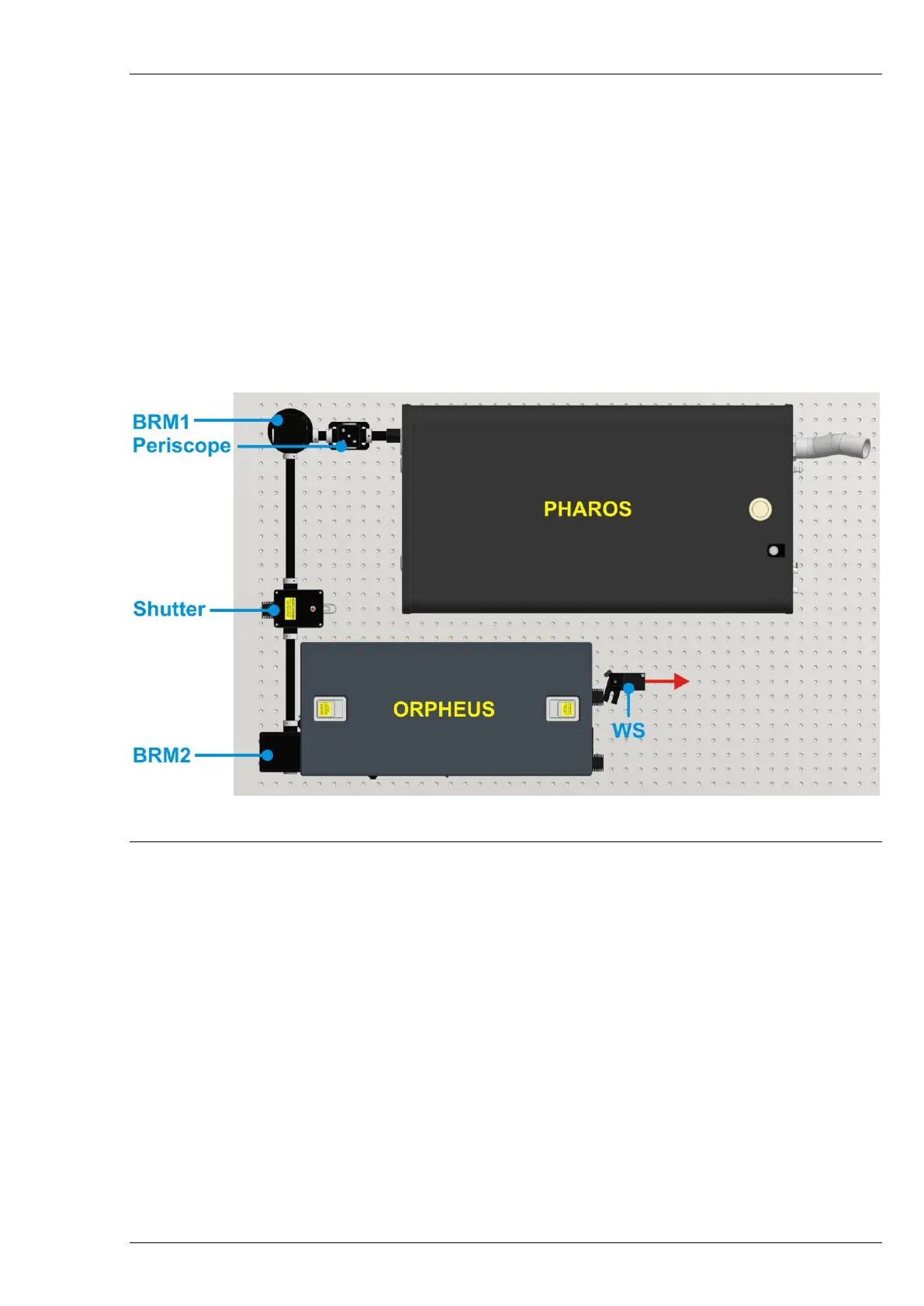
Figure 4 shows the recommended optical layout of ORPHEUS and pump laser. It is recommended to
position ORPHEUS along the side of optical table, about 5-20 cm from the table edge. Such a positioning
allows convenient access while aligning the device.
It is strongly recommended to fix all the system on the same optical table and as close as possible to
each other. Fixing the housings on a junction of the optical tables or letting the beam propagate several
meters until it enters ORPHEUS might increase the sensitivity of the system and/or lower the performance
especially in terms of long time scale instabilities.
Figure 4. Recommended layout of ORPHEUS with an external Signal pulse compressor
and pump laser
The beam from the amplifier is lifted to the input beam height level using a periscope. Depending on
the system layout, the periscope may direct the beam straight forward or at a 90 degree angle. Mirrors
BRM1 and BRM2 direct the beam to the ORPHEUS. The output beams exit the housing at the same height
as the input beam.
4.2 Fixing ORPHEUS on the Optical Table
ORPHEUS housing is fixed onto the optical table using special feet. The device freely rests on these
feet via three balls located on the ORPHEUS body. The feet are assembled into pads prepared for the width
and length of the ORPHEUS. They are fitted to the height of the pump beam and are not height adjustable.
The pads have 8 mounting holes each. Only two of them should be used for fixing to the optical
table. Figure 6 shows correct positioning of the feet on an optical table with 25 mm hole spacing. Figure 7
shows the correct positioning of the feet on an optical table with 1 inch hole spacing. Notice that in this
case, different mounting holes should be used.