ORPHEUS User’s Manual
26 support@lightcon.com Light Conversion
Correct pump intensity in Crystal 1 can be chosen rotating the half wave plate RP3. This should be
done during the device installation. Consult support team before performing any adjustments. An indicator
of sufficient pump intensity in the first amplification stage is super fluorescence originating from the
Crystal 1 crystal when the white light seed is blocked. You can check for SFL by placing a white card in front
of the M5/M6 periscope and setting 650 nm wavelength in the software. You may be able to see a part of a
red super-fluorescence ring (some of it is blocked by the M14 mirror). If the SFL is visible but the
amplification of the white light does not occur, it means that either the temporal or spatial overlap of the
pump beam and the WLC in the Crystal 1 is off. On the other hand, the SFL does not have to be visible for
amplification to occur.
5.6 Second Amplification Stage
The amplified portion of the white light continuum (seed) after exiting the first amplification stage
first travels through two delay plates DP2 and DP3. They are placed on a computer-controlled rotation
stage (“Delay 3” in the software) and are used to fine-tune the temporal overlap of seed and pump pulses
at the Crystal 2. Lenses L6 and L7 re-collimate the beam and adjust the diameter so that it matches the
diameter of the pump beam at Crystal 2. Dichroic mirror DM2 transmits the seed and reflects the pump
beam. After amplification at the nonlinear crystal, parametric radiation is separated from the pump beam
by mirror DM3 and is emitted from output port A of ORPHEUS.
The pump beam reflected by polarizer P2 and mirror M18 propagates to folding mirrors M19, M20
and M21. Beam height at these mirrors is 25 mm from the base plate. Half wave plate RP4 rotates the
polarization back to horizontal – needed for pumping nonlinear crystal Crystal 2. The beam then travels to a
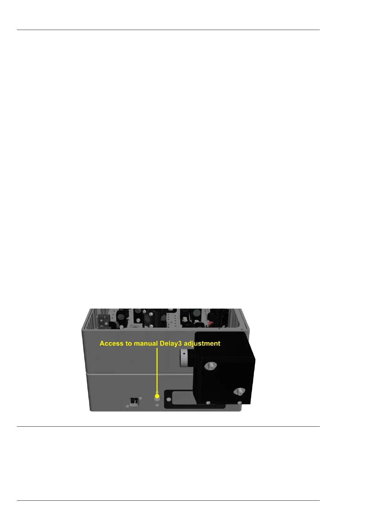
retro reflector M22/M23, which is placed on a manual translation stage. It is only necessary to adjust the
position of this stage after alignment or replacement of some optical components has been performed.
Tuning the position of these mirrors is required to ensure proper temporal overlap of pump and seed
beams at the Crystal 2. To adjust this translation stage first remove the screw at the input side of ORPHEUS
(see Figure 19), then use a 3 mm hex key to turn the micrometer screw.
Figure 19. Location of the manual Delay 3 adjustment protective screw
The intensity of the second pump beam is adjusted by lenses L12 and L13. These lenses are chosen
during installation of the device for fixed pump pulse parameters. The second harmonic pulse then
propagates to beam steering mirrors M24 and DM3 and into the nonlinear Crystal 2. This crystal is also
mounted on a computer-controlled rotation stage (“Crystal 2” in the software). As in the first amplification
stage, pump intensity at Crystal 2 is not far from the damage threshold for the BBO crystal. This limit