ORPHEUS User’s Manual
28 support@lightcon.com Light Conversion
One of the beams is transmitted through the first mirror and then blocked by the metal cover. If
necessary – this cover can be removed. The beams then travel in the same direction, separated horizontally
or vertically by ~13 mm (Figure 20).
Table 7. List of wavelength separators
Range of reflected wavelengths
5.9 Computer Controllable Motorized Stages
There are 6 automated stages inside the OPA device that control the angle or position of several
optical components.
Additional wavelength extension modules will require extra motorized stages. They are described in
the manuals of those modules. Currently, up to 12 motors can be controlled by a single USB control board.
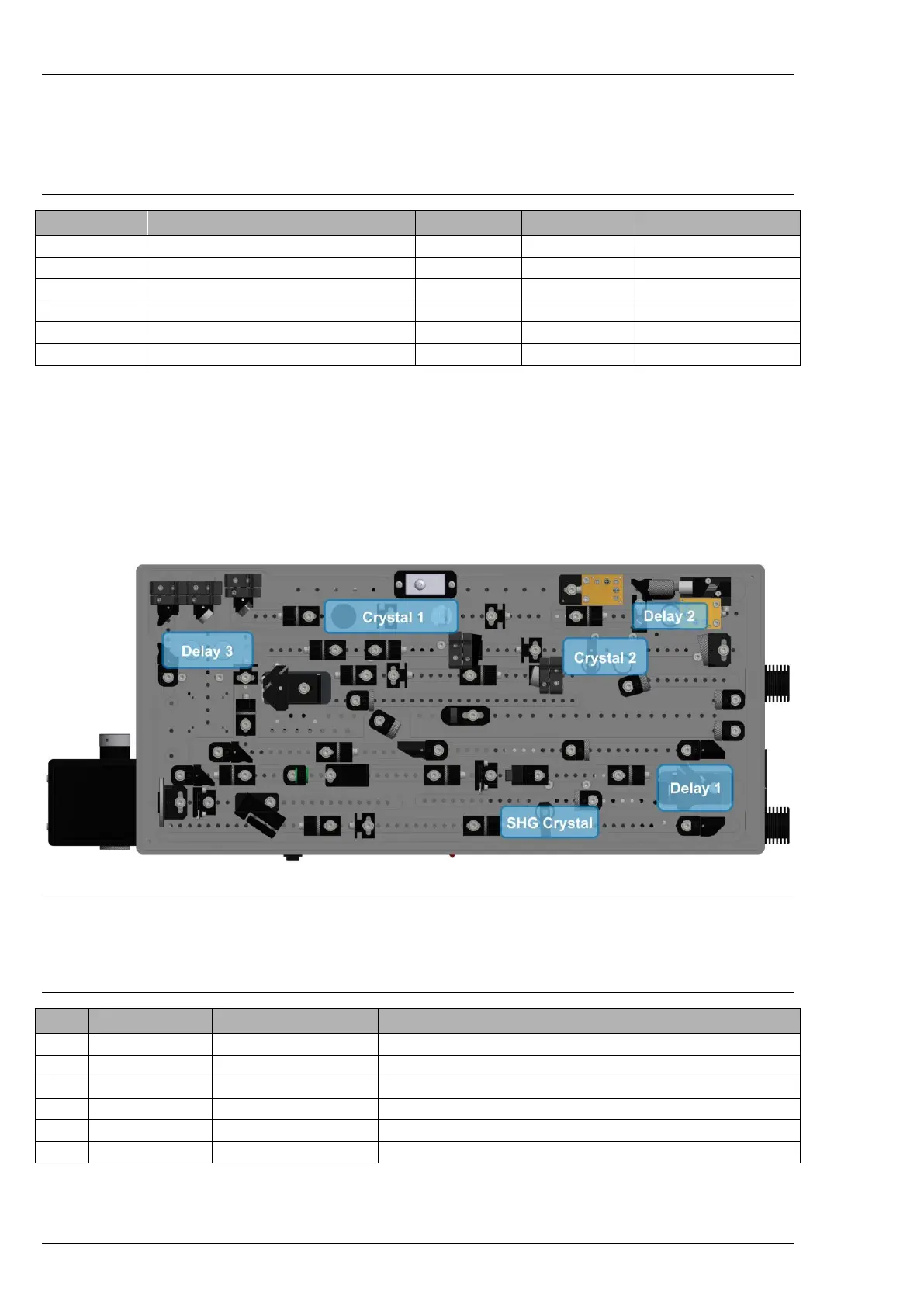
Figure 21. Location and names of the motorized stages inside ORPHEUS
The figure above shows the positions of the motorized stages, and the table below describes their
use in wavelength tuning.
Table 8. Names and descriptions of the motorized stages inside ORPHEUS
Pre-amplifier wavelength tuning
Pre-amplifier crystal phase matching angle
Pre-amplifier second pass temporal overlap
Power amplifier temporal overlap
Power amplifier crystal phase matching angle
Second harmonic (515nm) crystal angle