Never block the pump or second harmonic of pump beam
with a paper card. The card will ignite; the fumes may
gather onto the optical components and cause permanent
damage. When necessary, use metal beam blockers only.
M10 mirror reflects only the second harmonic radiation and directs it toward mirror M11. The
residual fundamental radiation is then blocked at the output port, or input into further wavelength
extension device. Beam height of the second harmonic at M11 is 20 mm. The beam then passes through a
rotator of polarization RP3 and polarizer P2. The beam transmitted through the polarizer (a smaller
fraction) is used for the first amplification stage, the reflected beam – for the second amplification stage.
Splitting ratio depends on the system configuration
5.5 First Amplification Stage
The pre-amplifier is used to produce stable and sufficiently bright seed pulses for the second
amplification stage. It employs a two-pass configuration using a single nonlinear Crystal 1.
The beam path of the pump in the preamplifier:
• first pass: L4-Crystal 1-L5-M14-M15-M16/M17
• second pass: M16/M17-M15-M14-L5-Crystal 1-C1-L4
The beam path of the white light continuum:
• first pass: L4-Crystal 1-L5-DP1-M5
• second pass: M6-DP1-L5-Crystal 1-C1-L4
5.5.1 The First Pass
The pump beam and WLC arrive at the lens L4 separated horizontally by 4 mm. The height of both
beams is 20 mm from the baseplate. The beams then travel below the compensator crystal C1 and into
nonlinear Crystal 1. The lens L4 focuses both beams into the same spot at Crystal 1 at the height of
22.5 mm, where amplification occurs. The wavelength of the amplified pulse is selected by tuning the
position of “Delay 1” stage and angle of “Crystal 1” in the software. The pump beam and the amplified
pulse then travel to the L5 lens where they are again separated by 4 mm, but now the beam height is
25 mm.
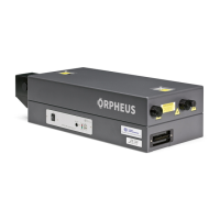
Figure 16. View of the first amplification stage from above
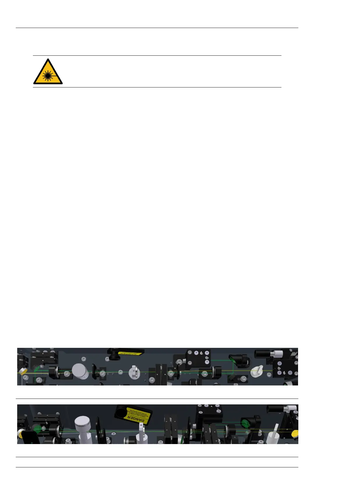
Figure 17. View of the first amplification stage from the side