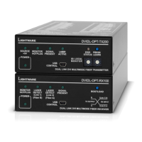
3. Product Overview DVIDL-OPT series – User's Manual 9
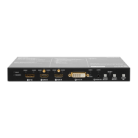
1
2 3 4
1
DVI input
29 pole DVI-I connector, however only digital
pins are internally connected. Connect single
link or dual-link DVI source with an applicable
DVI cable, use a dual-link DVI cable when dual-
link signal to be transmitted. The unit has
minimal cable compensation ability, hence the
maximum recommended cable length is 10
m. See the DVI Inputs and Outputs section for
more information.
2
5V DC input
5V DC input for local powering. The power
LED on the front indicates the proper supply
voltage. See more information about the power
connector in the DC 5V Connection section.
3
DVI output
29 pole DVI-I connector, however only digital
pins are internally connected. A local display
device can be connected to monitor the
outgoing signal. The resolution and pixel clock
frequency are the same on the DVI and Neutrik
connectors, no internal scaling or conversion
is applied to the signal. The OUTPUT connector
is able to supply 500 mA current on pin 14 to
DVI Inputs and Outputs section
for more information about DVI connector.
4
Neutrik
connector
Two channels are used for signal transmitting:
“Channel A” is used when single link video
signal is connected, while both “A” and “B”
channels are used when dual-link video signal
is connected to the input. See the Fiber Optical
Connector section for more information.
31 4
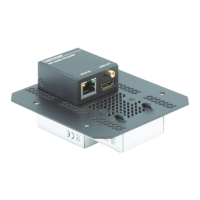
5 6
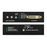
2
1
Monitor LED The LED indicates if a display device
(or repeater, etc.) is connected to the
corresponding DVI output and it sends a
valid Hot Plug Signal on Pin 16 through the
DVI cable.
2
Laser LEDs The LEDs indicate if a laser beam is detected
B”.
3
Signal LED Indicates if a valid DVI clock signal can be
4
Bootload
button
The receiver can be switched into bootload
more information in the Detailed Instructions
section.
5
Power LED Green LED indicates if the device is powered
on. It does not indicate whether the device is
operating properly.
6
USB
connector
Advanced EDID management (in LDC
via the USB interface. Use an USB cable with
mini-B male connector.
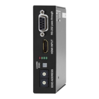
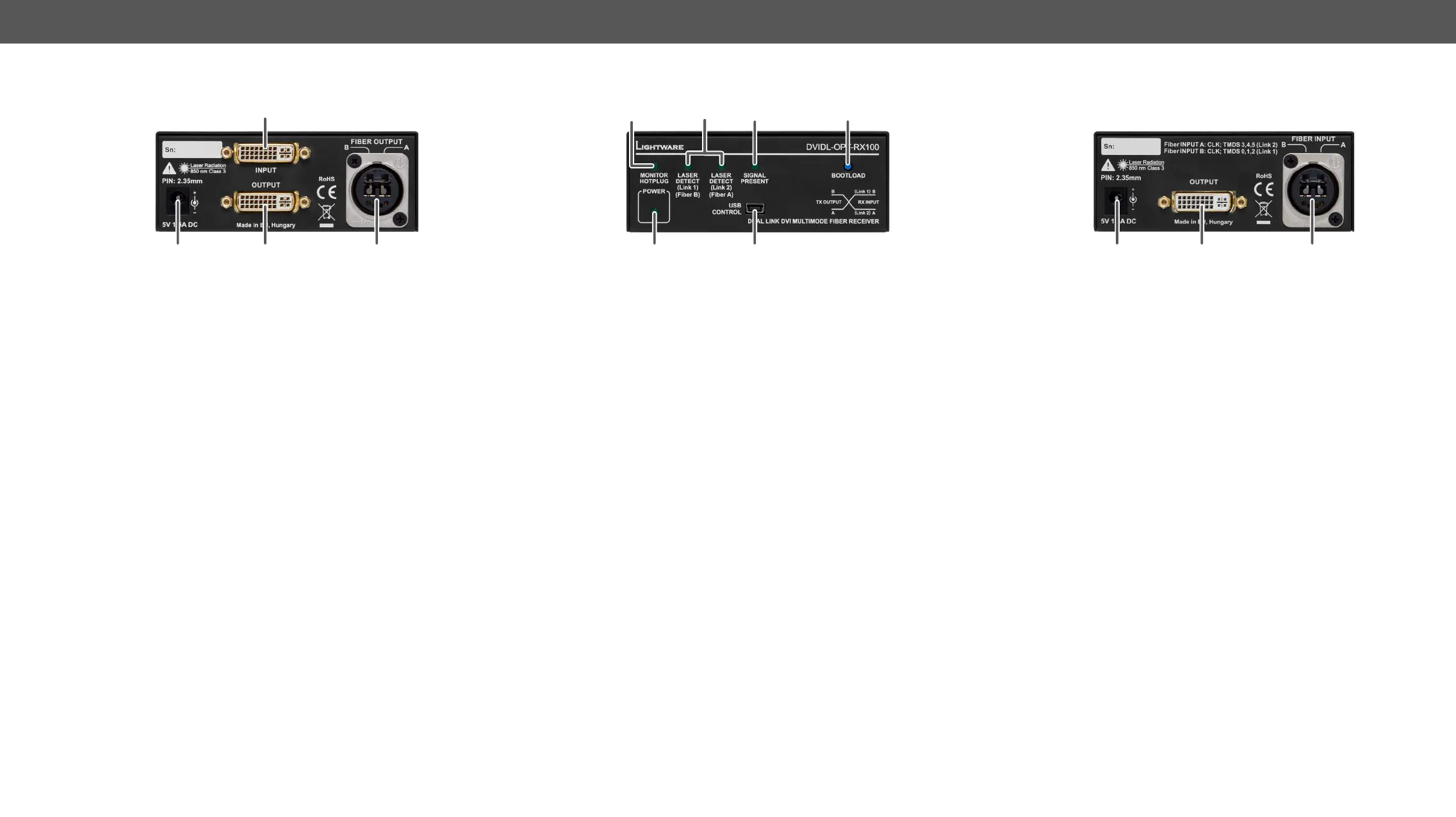
1 2 3
1
5V DC input 5V DC input for local powering. The power
LED on the front indicates the proper supply
voltage. See more information about the
power connector in the DC 5V Connection
section.
2
DVI output 29 pole DVI-I connector, however only digital
pins are internally connected. Connect
single link or dual-link DVI display according
to the signal with an applicable DVI cable.
The maximum recommended cable length
is 10 m. The OUTPUT connector is able to
supply 500 mA current on pin 14 to power
See the DVI Inputs and Outputs section for
more information about DVI connector.
3
Neutrik
connector
connector. Two channels are used for signal
transmitting: “Channel B” is used when single
link video signal is connected, while both “A”
and “B” channels are used when dual-link
video signal is connected to the input. See
the Fiber Optical Connector section for more
information.