3. Installation MMX4x2 series – User's Manual 24
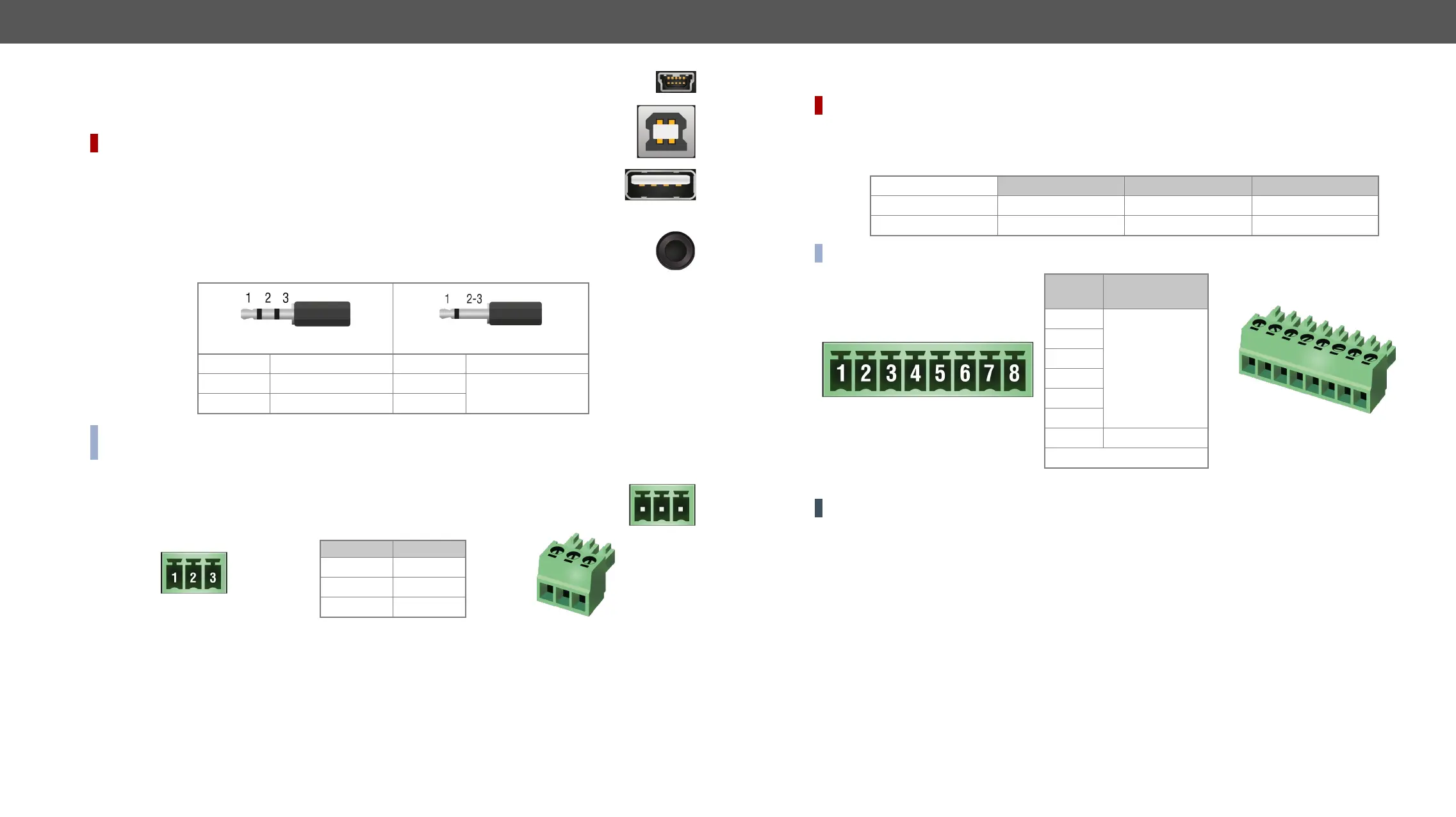
USB Connectors
The matrix provides a standard USB mini B-type connector on the front panel for device control
purposes.
DIFFERENCE:
USB 2.0 B-type ports are for connecting USB host devices (computers).
USB 2.0 A-type ports are for connecting USB peripherals (camera, multi-touch display, etc...).
IR Connector
An IR detector and an IR emitter can be connected to the matrix with TRS (Tip, Ring, and Sleeve)
and mini-jack plug. The pin assignments are the following for the detector and the emitter:
1 Tip Signal (active low) 1 Tip
2 Ring GND 2 Ring
Signal (active low)
3 Sleeve 3 Sleeve
INFO: Ring pole of the emitter is optional. If your IR emitter has a three-pole TRS plug, then the Ring and
the Sleeve carry the same signal (Output - ).
Messaging Options section.
RS-232 Connector
The matrix contains a 3-pole Phoenix connector, which is used for RS-232 serial connection.
Pin nr. Signal
1 Ground
2 TX data
3 RX data
RS-232 connector pin assignments
Compatible Plug Type
Phoenix
®
RS-232 Serial Interface section.
DIFFERENCE:
signal levels, and can be set to high or low level (Push-Pull). The direction of the pins can be input or output
Input voltage [V] Output voltage [V] Max. current [mA]
Logical low level 0 - 0,8 30
Logical high level 18
INFO: The maximum total current for the six GPIO pins is 180 mA.
Pin no.
Level and
direction
1
2
3
4
6
7
Ground
GPIO connector and plug pin assignments
ATTENTION! The sum of the current that the GPIO and the USB-A ports can supply together is max. 2A.
Compatible plug type
GPIO Interface section.
 Loading...