EasyManua.ls Logo

Lightware UMX-TPS-TX140

Lightware UMX-TPS-TX140
183 pages
To Next Page IconTo Next Page
To Previous Page IconTo Previous Page
Loading...
3. Installation UMX-TPS-TX100 series – User's Manual 33

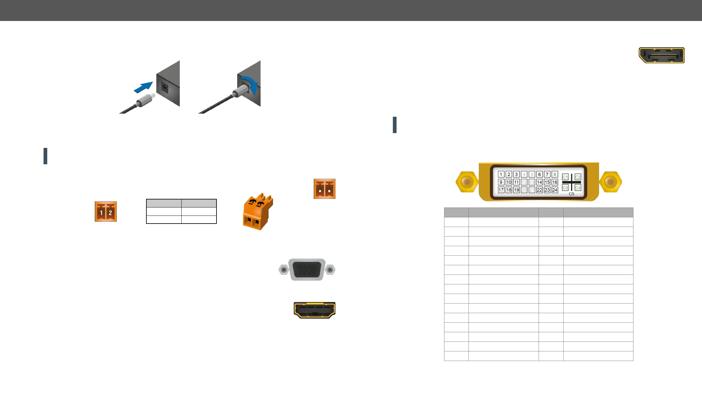
Electrical Connections
Locking 12V DC Connection
Locking DC connector

#power
WARNING! Always use the supplied 12V power adaptor. Warranty void if damage occurs due to use of a
different power source.
48V DC Connection

1A power connection.
2-pole Phoenix connector and plug pin assignments
VGA Connector
The transmitter provides a standard 15-pole D-SUB female connector for connecting
          

wires) is highly recommended.
HDMI Connector
The extender provides standard 19-pole HDMI connector for input. Always use high quality
HDMI cable for connecting sources and displays.
Pin nr. Signal
1 +
2 -
DisplayPort Connector
    

input. Always use high quality DP cable for connecting DisplayPort devices.
DVI-I Connector
UMX-TPS-TX130, UMX-TPS-TX140, UMX-TPS-TX140K and UMX-TPS-TX140-Plus transmitters provide a

               
audio) as well.
ATTENTION! 
to choose the input source.


signal pins.
Pin Signal Pin Signal
1 TMDS Data2- 16 Hot Plug Detect
2 TMDS Data2+ 17 TMDS Data0-
3 TMDS Data2 Shield 18 TMDS Data0+
4 not connected 19 TMDS Data0 Shield
5 not connected 20 not connected
6 DDC Clock 21 not connected
7 DDC Data 22 TMDS Clock Shield
8  23 TMDS Clock+
9 TMDS Data1- 24 TMDS Clock-
10 TMDS Data1+ C1 Analog Red
11 TMDS Data1 Shield C2 Analog Green
12 not connected C3 Analog Blue
13 not connected C4 Analog Horizontal Sync
14  C5 GND
15 

Table of Contents

Other manuals for Lightware UMX-TPS-TX140

Related product manuals