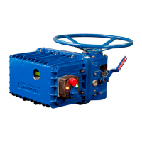
WTR Series
Installation Instructions
L120 Installation & Maintenance Manual 120-11000 A
Combination of Contacts
The rotor segments can be separated and rotated through 90 degrees to give various
combinations of normally open or normally closed contacts to each rotor.
1. Remove Nuts (piece #8) and Fillister Head Machine Screws (piece #5, for a total of 2
fasteners on each side of the switch).
2. Remove complete contact assembly from the back plate.
3. Rearrange cams on the camshaft to produce the required combination of contacts.
4. Replace contact assembly on back-plate (ensuring that the registers fit correctly) and secure
with the machine screw and nuts.
5. Set limits according to the procedure above.
Position Indication
Local position indication
The local dial position indicator is factory-selected to show valve position. The position
indicator can only be adjusted when mounted on the valve.
To set the local position indicator:
1. Disconnect all incoming power and remove Switch Compartment Cover (piece #200
of Figure 9).
2. Place the valve in the fully “close” position.
3. Loosen the round head machine screw which holds the pointer in place, move the pointer
to the “O” position, and re-tighten the screw.
The indicator is now set.
NOTE: The end-of-travel rotors of the geared limit switch activate “Flip-flop” type indicators.
This type of indicator will require no further setting after the geared limit switch has been adjusted.
Remote Position Indication
The L120 actuator with a position transmitter (PT20SD) installed, transmits a 4-20mA
output signal to a remote position indicator. The PT20SD responds to input of IK (ohms)
potentiometer and can be powered by 18VAC or 24VDC. For more information on this
transmitter, see 440-30001.
NOTE: The pinion has been left disengaged to prevent damaging of rheostat prior to
setting the valve. Set rheostat by turning pinion until the desired reading is obtained. Loosen
the hex nut on the back of the rheostat and slide the rheostat in the direction of the idler
pinion until pinions are engaged. Do not force engagement of the pinions. Re-tighten hex
nut on back of the rheostat. Do not engage pinion until unit and valve have been set.
9

 Loading...