WTR Series
Maintenance
L120 Installation & Maintenance Manual 120-11000 A
Optional Drive Sleeve
1. Remove the Handwheel (piece #29 of Figure 9), Handwheel Cover Plate (piece #33 of
Figure 9) and Gasket (piece #34) to provide access to the Elastic Stop Nut (piece #99).
2. Remove the Elastic Stop Nut (piece #99) from the Rod (piece #1). The Torque Nut
(piece #95) can now be removed from the bottom of the Drive Sleeve (piece #25 of
Figure 9).
3. The Torque Bushing Connector (piece #96) can be removed from the torque nut by
removing the Retaining Ring (piece #98).
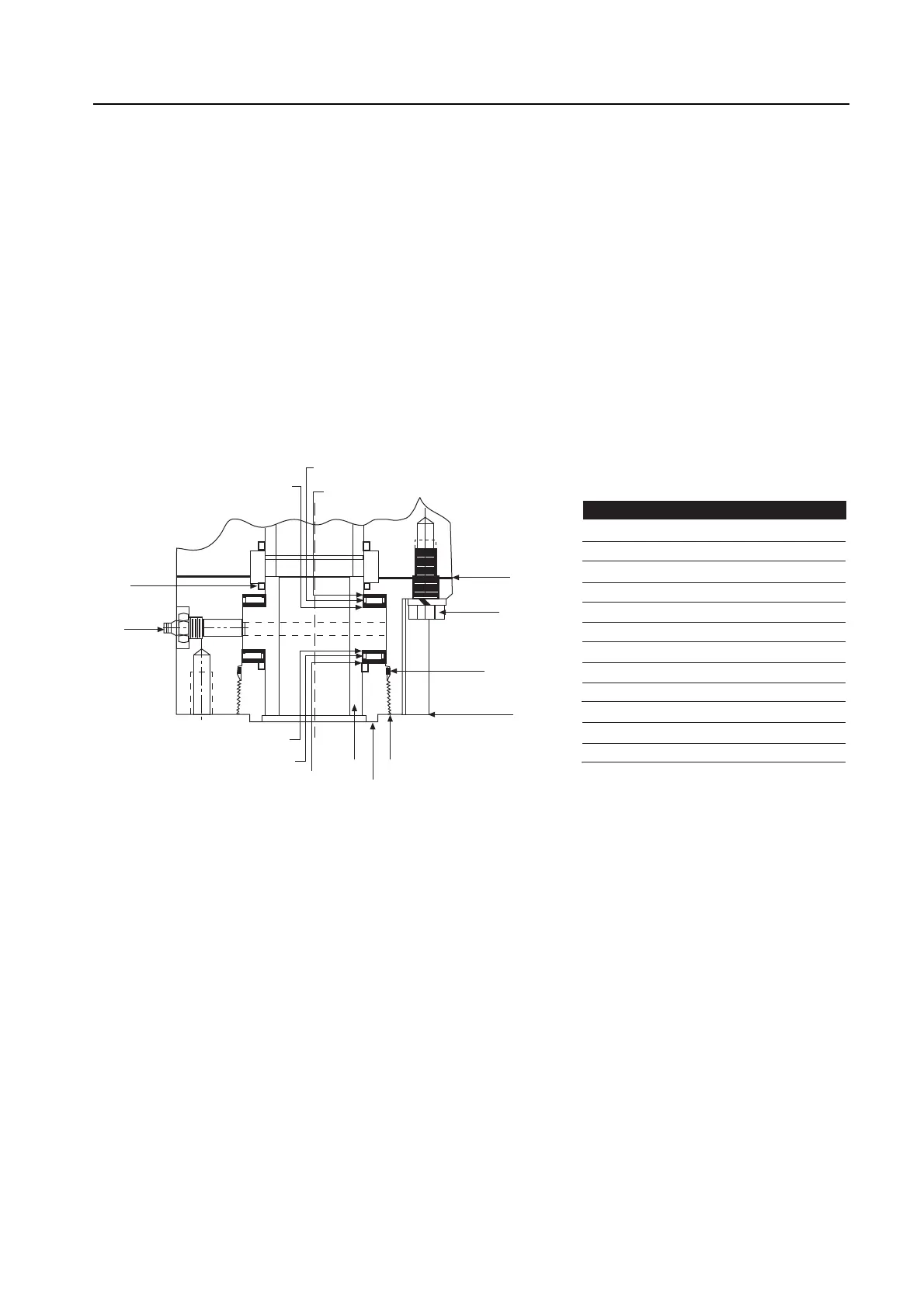
Thrust Base Disassembly (Drive 2 Option)
Figure 12 – L120-10 through 40 thrust base
Piece numbers refer to Figure 10.
1. If the Thrust Base (piece #100) option is present, remove the Seal Retainer (piece #102)
followed by Stem Nut (piece #101).
2. Remove the four Hex Head Cap Screws (piece #110) and the Lift Thrust Base from the
housing.
23