WTR Series
Installation Instructions
L120 Installation & Maintenance Manual 120-11000 A
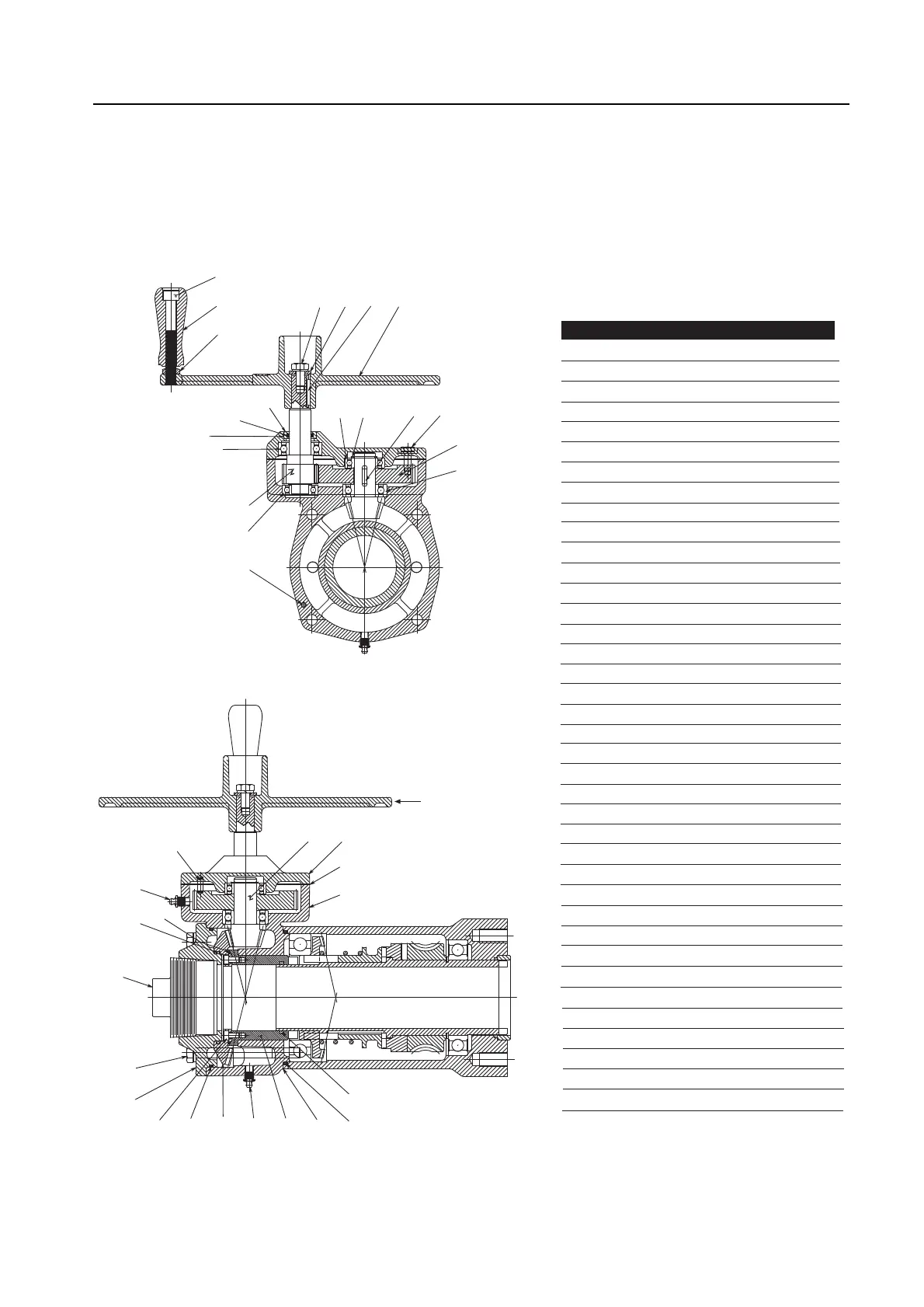
Figure 8 – L120-40 with side-mounted handwheel and parts list, attachment ratio 12:1
13
Handwheel Ratio 12:1
182-2
182-1
182-3
179
&
178
181
180
157-3
&
157-4
157-7
155
163
164
Note: Apply Loctite
601/609 to ID of
Bearing Cap
169
161
158-1
159
177
167
160
164
Sect. Thru Pinion
154
157-5
157-1
&
157-2
158-2
150
44
6
42-11
45
156
153
158-4
171
171
157-6
152
158-3
151
Piece Quantity Description
6 1 Housing Cover Shim
42-11 1 O - Ring
44 1 Quad Ring
45 1 Pipe Plug
150 1 Bevel Housing Cover
151 1 Bevel Housing
152 1 Spur Gear Cover
153 1 Bevel Gear
154 1 Bevel Pinion
155 1 Input Pinion Shaft
156 1 Bevel Gear Adapter
157-1 4 Hex Head Cap Screw
157-2 4 Lockwasher
157-3 4 Hex Head Cap Screw
157-4 4 Dowel Pin
157-5 8 Socket Head Cap Screw
157-6 2 Lockwasher
158-1 1 Quad - Ring
158-2 1 O - Ring
158-3 1 Gasket
158-4 1 Quad - Ring
158-7 1 Socket Head Cap Screw
159 1 Spur Gear
160 1 Ball Bearing
161 1 Seal Insert
163 1 Ball Bearing
164 2 Ball Bearing
167 1 Key
169 1 Retaining Ring
171 1 Grease Fitting
177 1 Handwheel
178 1 Hex. Head Cap Screw
179 1 Lockwasher
180 1 Key
181 1 Retaining Washer
182-1 1 Handwheel Spinner
182-2 1 Sock. Head Cap Screw
182-3 1 Hex. Jam Nut