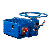
WTR Series
Operation / Maintenance
L120 Installation & Maintenance Manual 120-11000 A
Motor Operation
The actuator is always available for motor operation whenever the motor is energized
CAUTION: Do not force the declutch lever into motor operation. Lever will
automatically return to motor operation when the motor is energized.
Re-set the travel limit switches prior to motor operation if the unit has been dismantled or
removed from the valve.
Piece Numbers Refer to Figure 10, pages 17 amd 18.
In motor operation, the Motor Gear Set (piece #35 & 38) drives the Wormshaft (piece
#15) and Worm Gear (piece #21) which in turn rotates the Clutch Sleeve (piece #19) by
means of driving the lugs. The clutch sleeve and worm gear may be assembled to produce
either a “no lost motion” or “hammerblow” effect. The Drive Sleeve (piece #25) is keyed to
the clutch sleeve and hence rotates, producing the required output rotary motion.
Torque and Travel Limiting
The geared limit switch is driven by a bevel gear connected to the upper drive lugs of the
clutch sleeve. The limit switch is directly connected to the output of the actuator. Once
properly set, the limit switch remains in step with the valve position regardless of electric or
manual operation of the Limitorque actuator.
The worm and wormshaft are supported by two rotating spring packs. As torque is gener-
ated by the actuator, the worm moves axially against one of the spring packs. Each pack is
pre-calibrated and hence a finite compression represents a finite torque output. Movement of
the worm operates the torque switch, which interrupts the power to the motor. The torque
switch is adjustable and can be set to operate at pre-determined torque levels.
Maintenance
Lubrication
The L120 series actuators have a totally sealed gear case, factory lubricated with grease. The
gear case can be mounted in any position. However, those mounting positions that would
result in the operator area being saturated with lubricant if the seal fails should be avoided
and are not recommended.
No seal can remain absolutely tight at all times. Therefore, it is not unusual to find a very
small amount of weeping around shaft seals - especially during long periods of idleness such
as storage. Using grease minimizes this condition as much as possible. If a small amount is
weeping at start-up, remove it with a clean cloth. Once the equipment is operating on a
regular basis, the weeping should stop.
Lubrication Inspection
Inspect Limitorque L120 series actuators for correct lubrication prior to operating - particu-
larly following a long storage period.
Each application has its own effect on the actuator and the frequency of these inspections
should be based on the application and the operating experience. The following lubrication
inspection schedule is recommended until operating experience indicates otherwise.
For Gear Case, inspect lubrication every 18 months or 500 cycles, whichever occurs first.
19

 Loading...