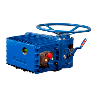
WTR Series
Maintenance
L120 Installation & Maintenance Manual 120-11000 A
Disassemble and Reassemble
CAUTION: Turn off all power services before attempting to perform service on the
actuator.
• Remove the actuator from the valve for complex work. Minor work, such as
replacing geared limit switch, torque switch or motor, may be readily performed
while the actuator is still on the valve.
• Potential High Pressure Vessel. Before removing or disassembling your actuator,
ensure that the valve or other actuated device is isolated and is not under pressure.
NOTE: If the actuator is fitted with a Thrust Base (piece #100 of Figure 10), it is possible to
remove the actuator housing while leaving the base on the valve to accept valve thrust.
However, it is preferred that the valve be isolated from service and, if it is a rising stem, that
the valve be fully open.
Disassemble Unit Sizes L120-10, 20, and 40
Unless otherwise noted, piece numbers refer to the Illustrated Parts Breakdown of Figure10.
1. Turn off power to the actuator.
2. Remove electrical Compartment Cover (piece #200).
3. Disconnect all electrical leads from the Torque Switch (piece #300) and Geared Limit
Switch (piece #305). Ensure that all leads and terminals are clearly marked to facilitate
reassembly.
4. Remove two screws holding limit switch and one holding torque switch. Remove both
items.
5. Remove four bolts holding Motor (piece #31) and three bolts holding conduit Nipple
Flange (piece #30). Remove motor, drawing motor leads through switch compartment.
6. Replace Motor Pinion (piece #38) by removing Stop Nut (piece # 40).
7. Remove Worm Shaft Gear (piece #35), Flexloc Nut (piece #37), and Worm Shaft End
Cap (piece #5) and draw complete wormshaft assembly from housing.
NOTE: The wormshaft has been assembled at the factory to obtain the correct pre-load
on the spring packs. Do not attempt to disassemble further. If the worm is worn or
damaged, it is suggested that the complete wormshaft subassembly be replaced. The
actuator must be in motor operation to remove the wormshaft assembly. When the
wormshaft is partially out, the disc springs will hit the worm gear. Pull the declutch lever
forward slightly without fully engaging the declutch mechanism and the wormshaft will
come out.
8. Remove Delutch Cap (piece #11).
9. For unit size L120-10, completely withdraw the Declutch Assembly (piece #7 of Figure
12) from the housing. For unit sizes L120-20 and 40, remove Declutch Input Pinion
(piece #12 of Figure 12) followed by the Declutch Assembly (piece #7 of Figure 12).
10. Remove Handwheel (piece #29) and Housing Cover (piece #27) and lift complete drive
sleeve subassembly from housing.
21

 Loading...