WTR Series
Maintenance
L120 Installation & Maintenance Manual 120-11000 A
Drive Sleeve and Housing Cover Disassembly
Piece numbers refer to Figure 9.
1. Remove Upper Ball Bearing (piece #17), Bevel Gear (piece #18), Declutch Spring (piece
#24), Clutch Sleeve (piece #19), and Key (Piece #23).
2. Remove Lower Ball Bearing (piece #16).
3. Spirolox Retainer (piece #22) may now be removed by inserting small flat blade
screwdriver under the end of the ring and prying the first layer from the groove.
Continue around the ring until it is free from the groove.
4. Remove the Wormgear (piece #21) and the Lug Ring (piece #20).
5. Handwheel Adapter (piece #26) and Seal (piece #42) can be removed from Housing
Cover (piece #27) by removing Retaining Ring (piece #28).
Torque Nut Disassembly (Drive 1 Option)
For applications requiring torque only, the L120 series actuator can be supplied without the
thrust base option. The torque nut is driven by the drive sleeve lugs and held in place by the
torque bushing connector.
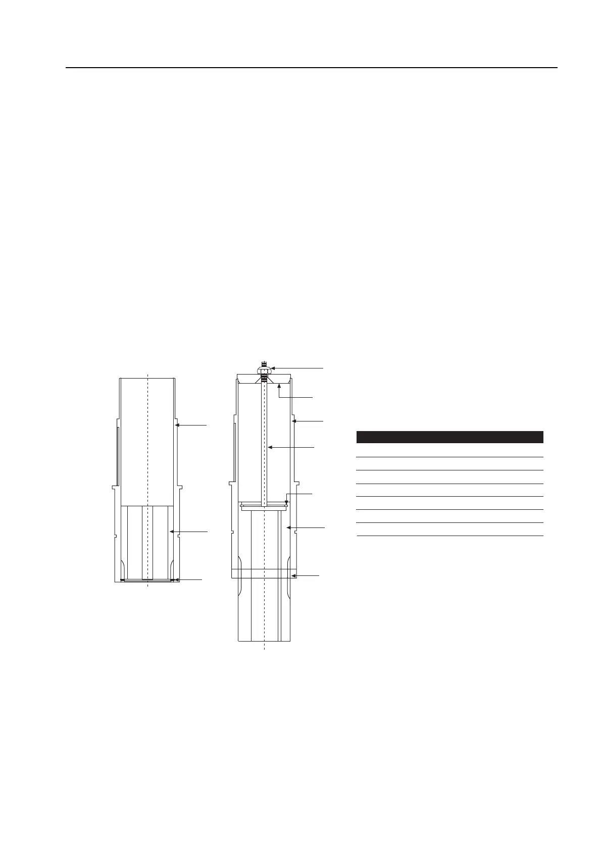
Figure 11 – L120-10 through 40 standard and extended drive sleeve assembly
Unless otherwise stated, piece numbers refer to Figure 11.
Standard Drive Sleeve
To remove the Torque Nut (piece #95), remove Retaining Ring (piece #183) and drop the
torque nut out the bottom of the Drive Sleeve (piece #25 of Figure 9).
22