WTR Series
Installation Instructions
L120 Installation & Maintenance Manual 120-11000 A
Geared Limit Switch
CAUTION: The geared limit switch is not preset at the factory and must be adjusted
after the actuator has been mounted on associated equipment.
• Disconnect all incoming power to the actuator prior to opening the limit switch
compartment and adjusting the switch.
• Consult the relevant wiring diagram for limit switch contact development. All L120
units are supplied with 16-contact limit switches - 4 switches on each of the 4 rotors.
Two rotors are used for end of travel indication. The remaining two rotors may be
adjusted for any intermediate point of travel.
• Do not use abrasive cloth to clean the contacts on the limit switch.
• Do not attempt to repair gearing in the limit switch. Replace entire gear frame
assembly if necessary.
Setting Limit Switch
NOTE: The standard 16-contact, 4-gear, limit switch is capable of counting up to 740 drive
sleeve turns depending on the actuator unit size. The Intermediate Shaft (B), shown in Figure
3, may take a considerable number of turns before rotor trip occurs.
a WARNING: Potential Explosion Hazard. Do not use a variable speed electric drill for
setting the limit switch in an explosive environment.
CAUTION: When setting the limit switch rotor segments (cams) using a variable speed
electric drill, do not run drill at speeds higher than 200 RPM. Operating the drill at
high speeds can damage the gearing within the limit switch.
Set the limit switch as follows. All item letters and piece numbers refer to Figure 3.
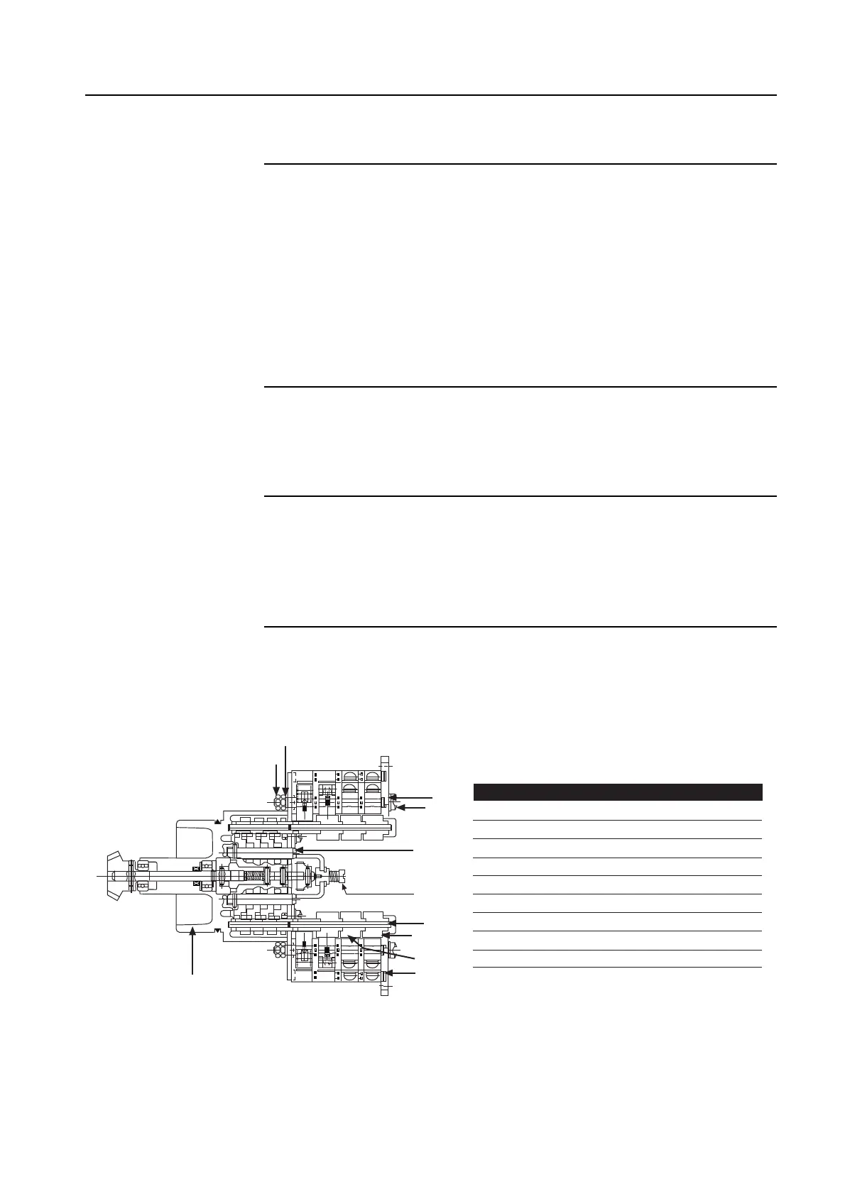
Figure 3 – Limit Switch
7
1
2
9
3
4
B
A
6
5
7
8
Limit Switch
Piece Quantity Description
1 1 Gear Frame Assembly
2 2 8-Switch Contact Block Assy.
3 12 Rotor Segment (short)
4 4 Rotor Shaft
5 4 Machine Screw
6 4 Flat Washer
7 4 Lock Washer
8 8 Hex Nut
9 4 Rotor Segments (long)