WTR Series
Installation Instructions
L120 Installation & Maintenance Manual 120-11000 A
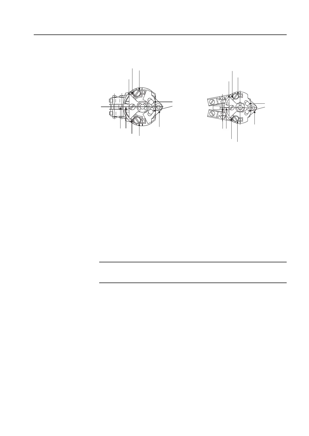
Figure 2 – Micro-Switch Style Torque Switch and 600 Volt Torque Switch
Balancing Torque Switch
Item letters correspond to Figure 2.
1. Place the actuator in manual mode.
2. Remove the load from the wormshaft spring pack.
3. Note the open and close torque switch settings prior to re-installing the torque switch.
4. Loosen screws (A) and position both pointers (B) at the #1 setting, tighten screw (A). In
this position the index marks should be aligned.
5. Loosen balancing screws and install the torque switch. The base of the torque switch
should be flush against the compartment and the hole for the mounting screw should be
aligned.
6. Install the mounting screw.
7. Tighten the balancing screws.
CAUTION: The balancing screws should not be touched except during the balancing
procedure.
The switch is now balanced and ready for the pointers to be returned to their original
settings.
6