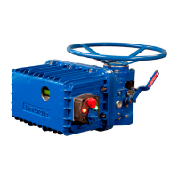
WTR Series
Installation Instructions
L120 Installation & Maintenance Manual 120-11000 A
Installation Instructions
Safety Precautions
a WARNING: Read this Installation and Maintenance Manual carefully and
completely before attempting to install, operate, or troubleshoot the Limitorque
L120 actuator.
a WARNING: Be aware of electrical hazards. Turn off incoming power before working
on the actuator and before opening switch compartment.
a WARNING: Potential HIGH-PRESSURE vessel – Be aware of high-pressure hazards
associated with the attached valve or other actuated device when installing or
performing maintenance on your L120 actuator. Do not remove the actuator
mounting bolts when the actuator is mounted on a rising stem valve unless the valve
is in the FULLY OPEN position and there is NO pressure in the line.
a WARNING: Do not manually operate the actuator with devices other than installed
Handwheel and Declutch Lever. Using force beyond the ratings of the unit and/or
using additive force devices such as cheater bars, wheel wrenches, pipe wrenches or
other devices on the actuator Handwheel or Declutch Lever may cause serious
personal injury and/or damage to the actuator or valve.
a WARNING: Do not work on actuator while it is mounted on a torque-seated valve.
Safety Practices
The following check points should be performed to maintain safe operation of the L120
actuator.
• Mount motors on a horizontal plane, if possible.
• Keep the switch compartment clean and dry.
• Keep the valve stem clean and lubricated.
• Set up periodic operating schedule for infrequently used valves.
• Verify all unit wiring is in accordance with the applicable wiring diagram.
• Carefully check for correct motor rotation direction. If the motor is driving the valve in
the wrong direction, interchange any two leads on three-phase motors or switch the
armature leads on D.C. and single-phase motors.
• Use a protective stem cover. Check valve stem travel and clearance before mounting
covers on rising stem valves.
Prepare Initial Actuator
Replace all molded plastic conduit and top protectors (installed for shipping purposes only)
with pipe plugs when installation wiring is complete.
Mounting Base
The mounting hole sizes and quantities are as detailed in Table 2.
Table 2 – Mounting Base Dimensions
Mounting Holes Tap size
Unit Size Quantity MSS ISO
L120-10 4 3/8-16x0.88 M10x1.5x22.4
L120-20 4 5/8-11x1.25 M16x2x32
L120-40 4 5/8-11x1.25 M16x2x32
4

 Loading...