WTR Series
Maintenance
L120 Installation & Maintenance Manual 120-11000 A
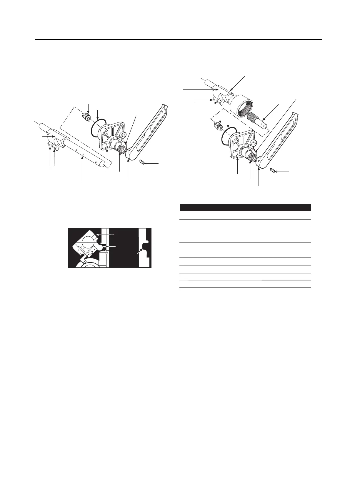
Figure 13 – L120-10 through 40 declutch assembly parts breakdown
Declutch Assembly (L120-10)
8. Install Declutch Cap (piece #11) on the Declutch Shaft (piece 7A). Ensure that the
return spring is located correctly in the endcap.
9. Replace Declutch Lever (piece #9) on the shaft with the lever against the stop.
10. While holding the cap steady, rotate the declutch shaft against the spring tension until
the holes in the shaft and lever align.
11. Replace complete assembly in main housing. Ensure that the lug on the
Declutch Actuator (piece #7-1) fits into the groove on the Handwheel Clutch Sleeve
(piece #19 of Figure 10).
12. Secure the declutch cap.
NOTE: When the declutch lever is disengaged against the declutch stop (motor
operation position), the Declutch Actuator (piece #7-1) should not be in contact with
the groove on the Handwheel Clutch Sleeve (piece #19 of Figure 10).
25
10
42
11
42
12
7
7-2
&
7-3
7-1
Declutch Stop
8
9
7A
L120-10
L120-20/40
9
8
10
42
11
42
Declutch Stop
Piece Quantity Description
7* 1 Declutch Shaft Assembly L120-20/40
7A 1 Declutch Shaft Assembly
7-1 1 Declutch Actuator
7-2 & 7-3 1 Declutch Latch (left & right)
8 1 Declutch Return Spring
9 1 Declutch Lever
10 1 Roll Pin
11 1 Declutch Cap
12* 1 Declutch Input Pinion
42 1 Seal
*L120-20/40 only
7-2
&
7-3
7-1
LUG
Declutch
Actuator
Handwheel
Clutch
Sleeve