Page 41 of 192
Input/Output specifications: Dual Hall positioning PNP (03 in ordering example)
The Dual Hall positioning PNP is an option on LA23. This is especially suitable for wheelchairs or Techline applications as the LINAK control boxes
have their own option 02 for that purpose.
• Is protected against loaddump and wrong placement of wires
Input/Output specifications: Dual Hall positioning PNP
Item Specification Comment
Description The actuator can be equipped with two hall sen-
sors A and B and a spindle magnet. In this way you
can have pulses from the actuator when it moves.
Input voltage 9-32VDC Feedback circuit has to be powered 1 second before driving
and until the actuator has stopped.
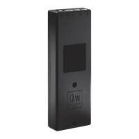
Output voltage PNP source current: max. 12mA.
HIGH: Output = VCC-1.2V (±0.5V)
LOW: Output = 10KΩ pull down
tRISE < 100us
@24V LOAD:5m cable 1nF//10KΩ
tFALL < 100us
@24V LOAD:5m cable 1nF//10KΩ
tstate > 10ms
@24V LOAD:5m cable 1nF//10KΩ
Current Max. 20mA+source current. Also when actuator is not running.
Protection LOAD DUMP
Wire wrong placement
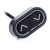
Resolution The feedback system has an 8P magnet which
gives 16 shifts in pulses per spindle turn:
3 mm pitch = 0.1875 mm per pulse
6 mm pitch = 0.375 mm per pulse
9 mm pitch = 0.5625 mm per pulse
12 mm pitch = 0.75 mm per pulse
20 mm pitch = 1.25 mm per pulse
See drawing for details.
Tstate is minimum 5ms in all states (11.10.00.01)
On 100 mm stroke you will have
the following number of pulses:
3 mm pitch = 533 pulses
6 mm pitch = 267 pulses
9 mm pitch = 178 pulses
12 mm pitch = 133 pulses
20 mm pitch = 80 pulses
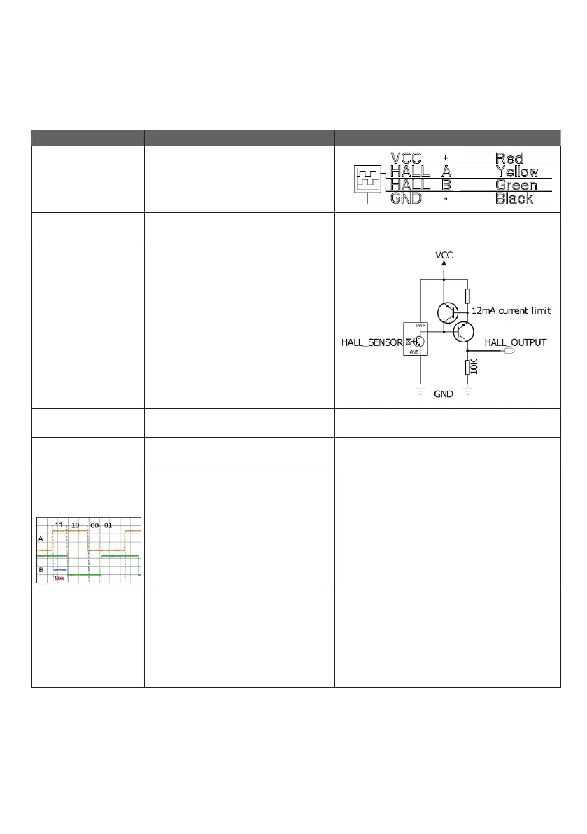
Cable Connection
M+: Brown
M-: Blue
VCC: Red
HALL A: Yellow
HALL B: Green
GND: BLACK
Max. length 5m.
Use cables:
Standard 6 wires:
0237002-xxxx