Page 242 of 295
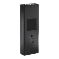
The modular junction box MJB5 Plus is designed for use together with OpenBus™
control boxes.
The MJB5 Plus makes it possible to connect multiple hand controls and attendant
controls. It can even be used for charging or to connect the Under Bed Light and 3
rd
party products.
MJB5 Plus with Under Bed Light (ext.) and Switch Input
MJB5 Plus versions 506-010 and 506-020:
The MJB5 Plus is a modular junction box with 3 different options, Under Bed Light
(UBL) and two switch inputs, S1 and S2, which can be used for an external switch.
UBL: The MJB5 Plus with UBL is a simple solution to prevent fall accidents and make
the patient feel safe. The UBL makes it easy to find the way back to the bed at night
without disturbing other patients.
The MJB5 Plus has an external LED cable (0964135) which is connected to Port 5.
The external LED cable makes it more flexible to use the UBL. It can be moved from
side to side of the bed or can be placed at the foot of the bed.
External Switch (S1/S2): It is possible for the customer to connect a switch directly
to the MJB5 Plus. It can be used with a customised switch or control.
Usage
Compatibility: All OpenBus products
Operation temperature: +5
o
C to +40
o
C
Storage temperature: -10
o
C to + 50
o
C
Relative humidity: 20% to 80% non-condensing
Atmospheric pressure: 700 to 1060 hPa
Operational meters above sea level: Max. 3000 meters
Latex free: Yes
Approvals: IEC60601-1, ANSI/AAMI ES60601-1, CAN/CSA-22.2 No 60601-1,
Standard functionality:
UBL: The UBL LED can be switched on and off via the patient control (Key1) or the attendant control (Key2).
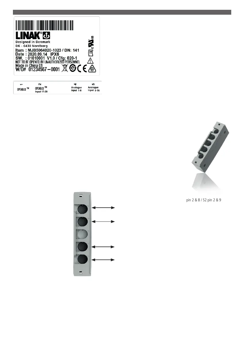
External Switch (S1/S2): The external switch is connected to S1: Pin 2 & 8/S2: Pin 2 and 9 on Port 2, Port 4 or Port 5.
The switch input functionality can be enabled/disabled via the attendant control. The enable/disable status (switch status) is indicated on the OpenBus.
The switch input functionality is as standard to be used with a NO switch. When the switch is activated (NC), a notification is sent on the OpenBus (switch
notification).
Port 5
Port 4
Port 2
Port 1
OpenBus™ connection / Ext. UBL cable / S1 pin pin 2 & 8 / S2 pin 2 & 9
OpenBus connection / S1 pin 2 & 8 / S2 pin 2 & 9
OpenBus connection / S1 pin 2 & 8 / S2 pin 2 & 9
OpenBus connection
Port 3 is not available
13. MJB5 Plus UBL (ext) (MEDLINE
®
CARELINE
®
)
 Loading...