Page 52 of 295
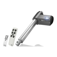
The LA27 actuator is a powerful actuator designed for a variety of medical applications.
It is developed for both push and pull applications and has a very robust construction
because of the ultrasonic welded plastic housing.
Usage
• Duty cycle: 2/18; 2 minutes continuous use followed by 18 minutes not in use
• Ambient temperature: +5
o
C to +40
o
C (the actuator must also have this temperature)
• LA27 is approved in accordance with IEC 60601-1, ANSI/AAMI ES 60601-1 and
CAN/CSA C-22.2 No. 60601-1
• With connection to a static voltage power supply of 33V the lifetime could be
reduced to 5000 cycles (at a constant load of 6000 N).
The product is not designed for dynamic load changes (from push to pull or vice versa.
If the application design requires a product with a dynamic load change capability,
please contact LINAK for investigation of product feasibility or guidance.
Note: For CB6, the current will be cut off when the total current on all channels reaches approx. 5.1 to 5.4 Amp. This means that when two LA27s,
running simultaneously, are connected to a CB6, they will not be able to lift the max. load mentioned under technical specifications.
Recommendations
• The LA27 cable is not part of the actuator and must therefore be ordered separately.
• Once a year, the actuator must be inspected for wear and jarring sounds.
• In medical applications we recommend to use a safety nut.
• Do not expose actuators without all cables fitted to water/cleaning.
• The bolt inside the back fixture should have no thread.
• LA27 is not meant to have CB6S OBF mounted on the actuator.
CB6S OBF must be mounted separately using a bracket.
• LA27 must have a minimum installation dimension of 320 mm if control box CB6 is to be mounted on the actuator.
5. LA27 (MEDLINE
®
CARELINE
®
HOMELINE
®
)
Warning
• The installation of spline actuators is recommended by LINAK where possible to avoid the squeezing of body parts.
• Activation of a quick release can lead to a risk of squeezing body parts. Installation of a damper may reduce this risk.
• A quick release can accidentally be activated during mounting or maintenance. To avoid this, operators must be warned before service/mounting.
• End of life issue: defective switches - endstop:
If the electrical endstop switch for outward operation fails, it may cause a prolonged actuator stroke and in addition the customer application may
collapse. To avoid this, the manufacturer must take this into account when designing and making a risk analysis.
• If electrical endstop fails to function the actuator will continue to retract or extend until mechanical endstop is reached.
The application of the customer must be able to obtain or withstand an actuator with failing electrical endstop.
Minimum length of actuator reaching mechanical endstop: BID - 5 mm.
Maximum length of actuator reaching mechanical endstop: BID + SL + 5 mm.
• If the actuator does not work as intended, there is a risk of injury. Therefore, the actuator must immediately be sent to the nearest authorised
LINAK workshop for service.
• The actuator is not designed for repeated dynamic push-to-pull movement.
Instruction concerning the turning of the piston rod eye – LA27
When mounting and taking into use, it is not permitted to make excessively many turns of the piston rod eye. In cases
where the eye is not positioned correctly, it is permitted to first screw the eye down to its bottom position (1), and
then a maximum half turn outwards again (2).