Page 274 of 295
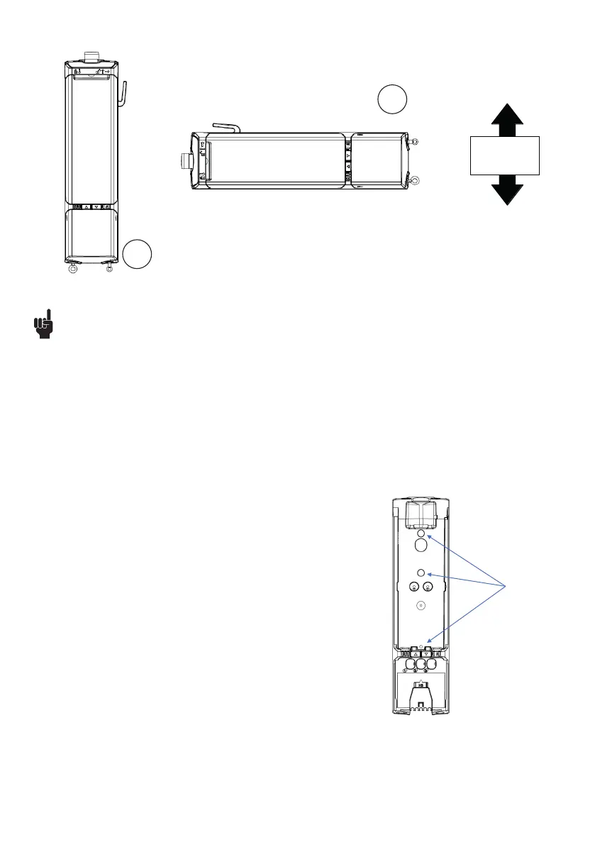
Mounting holes
Front view
When mounting CAL40 or CAL40+ on a patient
lift, please use at least two of the three
dedicated mounting holes placed in body of
charger.
CAL40 – Mounting on Patient Lift
LIFT40 only complies with IPX6 when the control box is mounted correctly (see illustration 1 and 2).
LIFT40 can be mounted as shown on the pictures above:
• Battery upwards, cable outlets downwards (see illustration 1)
• Control box lying on the right side, seen from the front (see illustration 2)
Cables and blind plugs must be inserted correctly in the control box to maintain the IP degree in washing or cleaning situations.
LIFT40 mounting
Recommendations - positioning
Mounting information:
LIFT40 is mounted by means of minimum 2 screws (not supplied by LINAK).
Screw type: ISO7380-1 / M5 and L = 20 mm or 25 mm
Washer type:
ISO7089 / M5, d1 = 5.3 mm / d2 = 10 mm / s = 1mm
The LIFT40 control box must be mounted with minimum two of the three screws possible.
The mounting screws for the control box and the charger must be tightened with a
maximum torque of 1 Nm.
When mounting CAL40 or CAL40+ on a patient lift, please use at least two of the three
dedicated mounting holes in the charger body.
1
2
 Loading...