95
Table of Contents
Linksys
Table of Contents
Linksys
• 802.1p—Displays the 802.1p priority tag values to be assigned to an
egress queue, where 0 is the lowest and 7 is the highest priority.
• Output Queue—Select the egress queue to which the 802.1p priority is
mapped. Either four or eight egress queues are supported, where Queue
4 is the highest priority egress queue and Queue 1 is the lowest priority.
STEP 3 For each 802.1p priority, select the Output Queue to which it
is mapped.
STEP 4 Click Apply. 801.1p priority values to queues are mapped, and the
Running Configuration file is updated.
DSCP to Queue
The DSCP (IP Differentiated Services Code Point) to Queue page maps DSCP
values to egress queues. The DSCP to Queue Table determines the egress
queues of the incoming IP packets based on their DSCP values. The original
VPT (VLAN Priority Tag) of the packet is unchanged.
By simply changing the DSCP to Queue mapping and the Queue schedule
method and bandwidth allocation, it is possible to achieve the desired quality
of services in a network.
The DSCP to Queue mapping is applicable to IP packets if:
• The device is in QoS Basic mode and DSCP is the trusted mode,
Non-IP packets are always classified to the best-effort queue.
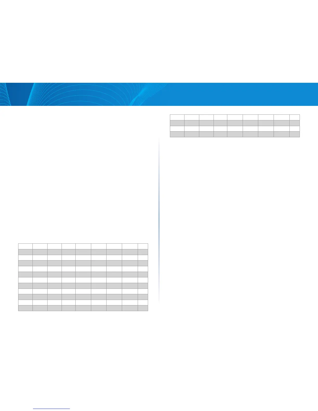
The following tables describe the default DSCP to queue mapping:
DSCP 63 55 47 39 31 23 15 7
Queue 3 3 4 3 3 2 1 1
DSCP 62 54 46(EF) 38(AF3) 30(AF33) 22(AF23) 14 6
Queue 3 3 4 3 3 2 1 1
DSCP 61 53 45 37 29 21 13 5
Queue 3 3 4 3 3 2 1 1
DSCP 60 52 44 36(AF42) 28(AF32) 20(AF22) 12(AF12) 4
Queue 3 3 4 3 3 2 1 1
DSCP 59 51 43 35 27 19 11 3
Queue 3 3 4 3 3 2 1 1
DSCP 58 50 42 34(AF41) 26(AF31) 18(AF21) 10(AF11) 2
Queue 3 3 4 3 3 2 1 1
DSCP 57 49 41 33 25 17 9 1
Queue 3 3 4 3 3 2 1 1
DSCP 56(CS7) 48(CS6) 40(CS5) 32(CS4) 24(CS3) 16(CS2) 8(CS1) 0(BE)
Queue 3 3 4 3 3 2 1 1
The queue 4 is the highest queue and the default classes in the parentheses
are defined by IETF.
To map DSCP to queues:
STEP 1 Click Configuration > Quality of Service > DSCP to Queue.
STEP 2 Select the Output Queue (traffic forwarding queue) to which the
DSCP value is mapped.
STEP 3 Click Apply. The Running Configuration file is updated.
Bandwidth Control
The Bandwidth Control page enables users to define two values, Ingress Rate
Limit and Egress Shaping Rate, which determine how much traffic the system
can receive and send.
The ingress rate limit is the number of bits per second that can be received
from the ingress interface. Excess bandwidth above this limit is discarded.
The following values are entered for egress shaping:
• Committed Information Rate (CIR) sets the average maximum amount
of data allowed to be sent on the egress interface, measured in bits per
second
• Committed Burst Size (CBS) is the burst of data that is allowed to be sent,
even though it is above the CIR. This is defined in number of bytes of data.
To enter bandwidth limitation:
STEP 1 Click Configuration > Quality of Service > Configure > Bandwidth.
Control
The Bandwidth page displays bandwidth information for each interface.
STEP 2 Select an interface, and click Edit.
STEP 3 Select the Port or LAG interface.
STEP 4 Enter the fields for the selected interface:
• Ingress Rate Control—Select to enable the ingress rate limit, which is
defined in the field below.
 Loading...