Fig. 9
Fig. 10
Fig. 11
Fig. 12
Fig. 13
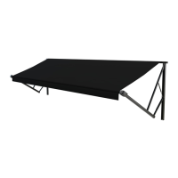
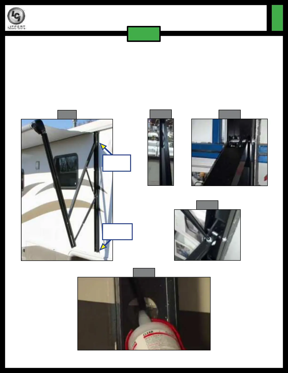
12. Starting at the motor, run the wire approximately halfway down the outer arm, then up the inner
arm to the wall mount (holes for ‘top wire’ and ‘bottom wire’ options are provided in the wall mount
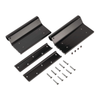
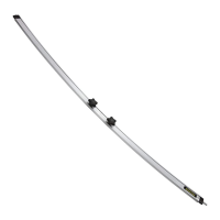
extrusion) (Fig 9). Install plastic wire covers into the outer arm (1 section), inner arm (2 sections), and
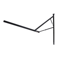
wall mount (2 sections) extrusions to secure/protect the power supply wire (Figs 10-12). Make sure
wire is placed on the outside of the pin that joins the steel tension arm to the wall mount (Fig. 12) to
prevent damage to the wire.
13. Hook power cord to the coach supplied power.
14. Seal all wall penetrations to protect against water intrusion (Fig. 13).
CONVERSION FROM MANUAL
PULL STRAP TO POWER AWNING
TI-164
AWNINGS
Bottom
Wire Stop
Top Wire
Stop