LITE-CHECK INSPECTOR 930
23
lower, it may indicate wire corrosion. New trailers must provide the correct voltage to
their Antilock Braking System (ABS) and electronic control unit (ECU) through both
the stop lamp circuit and the continuous power circuit. The specified value of 9.5
volts for minimum voltage includes a safety margin of 1.0 volt.
1. Connect the tester to the trailer with the 7-Way vehicle cable.
2. Press “SELECT” button. (This will allow the tester to test multiple added
loads.)
3. Record tester voltage and amperage. (It should be 00.00 at this step.)
4. Press the following buttons in order
a. “MARKER”
b. “LEFT”
c. “TAIL”
d. “RIGHT”
e. “BRAKE”
f. “AUXIL”
5. Record circuit voltage and amperage.
6. Press “SELECT” button to cancel the test.
NOTE: A similar feature is available in the SPECIAL
FUNCTIONS tab under ABS.
ABS Operation
Warning: If the trailer being tested has multiple ECUs,
before beginning the ABS test procedure, disconnect all
but one ECU. Run the ABS test procedure using the
steps below. When completed, disconnect the first ECU
and connect the next one. Now repeat the test
procedure with the next ECU.
NOTE: Most ABS notes in this section are for
Haldex PLC4Trucks. Other ECUs may vary.
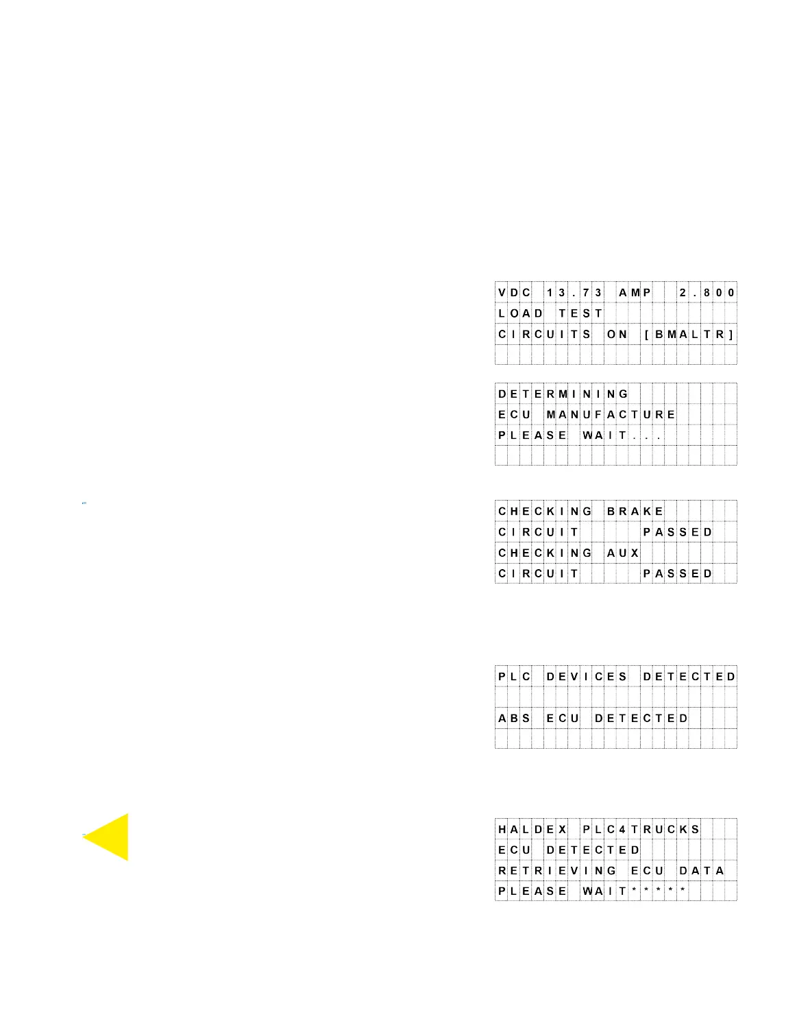
The INSPECTOR 930 automatically checks the brake
and auxiliary circuits.
Press the yellow ABS button on either the
ABS
keyboard or the remote. The tester will display the
BACK
brake and auxiliary circuits’ status for a moment.
NOTE: If the brake circuit test fails, the operator will be
given the option of continuing or exiting the test. If the
auxiliary circuit test fails, the display will indicate an error