CHAPTER 8: OPERATION
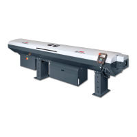
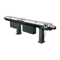
ALPHA ST 320
8-7
To select Functions 5 – 8 (F5 – F8):
Step 1: Press Shift
Step 2: Press F5 , F6 , F7 or F8
Step 3: Press Enter
Step 4: Press ▲ or ▼ to change parameter
Step 5: Press Enter to confirm the change
3.1 Parameter F1~F8 display and description
3.1.1 F1 : Bar Diameter
F 1 : B A R D I A M E T E R
( 3 - 2 6 m m ) :
The bar stock size, for example, 10mm in diameter is set and memorized in the PLC. The value of F1
ranges from 3 to 20mm and is always an integer number.
3.1.2 Clamp Openings / F2 : Part Length
P A R T F O R C H U C K S =
F 2 : P A R T L E N G T H =
Part for Chucks:This value indicates whether an additional chuck opening/closing is required to make
one work piece. Only the values 0 (=no additional chuck opening/closing) or 1 (= one additional
opening/closing) are allowed. (This parameter is only used when the lathe does not provide interface
signal A3)
F2:Set this value to the work piece length + tooling width. E.g. Work piece length is 20mm and the width
of the cutting tool is 2mm Æ part length = 22mm. With every work piece the remaining bar length is
reduced by 22mm.
3.1.3 F3 : Guiding Channel Diameter
G U I D I N G C H A N N E L D I A -
M E T E R : 8 - 2 9 m m F 3:
Guiding channel size:This value affects the pushing force. It should correspond to the actual channel
size (the channel size is marked on the channel).
 Loading...