CHAPTER 7: GENERAL DESCRIPTION
ALPHA ST 320
7-4
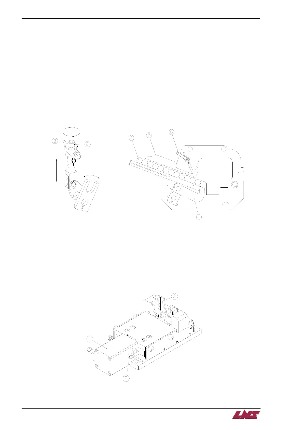
2. LOADING RACK
The loading rack is actuated by a pneumatic cylinder. The loading finger (Fig 7.3 #1) is moving up to load
a new bar. The position can be adjusted for different size materials by adjusting the screw (Fig 7.3 #2).
Tighten wingnut (Fig 7.3 #3) to lock into position.
To avoid bar stock (Fig 7.3 #4) overlap, the plate limit position (Fig 7.3 #5) can be adjusted. Loosen the
knob (Fig 7.3 #6) to release the plate. Adjust about 2 mm from the material and tighten knob (Fig 7.3 #6).
Repeat the operation for each plate.
Fig. 7.3
3. VISE
The vise is actuated by a pneumatic cylinder (Fig 7.4 #1). It does not need to be adjusted for each bar
diameter. The sensor LED (Fig 7.4 #2) is only ‘ON’ when the vise is closed without bar between the jaws
(Fig 7.4 #3).
Fig. 7.4
 Loading...