CHAPTER 8: OPERATION
ALPHA ST 320
8-9
3.1.8 Pusher Move Pos / First Feed
P U S H E R M O V E P O S =
F 8 : F I R S T F E E D =
Pusher move position: Defines the distance that the pusher moves forward to insert the bar into the finger
chuck. The value range is from 20 to 50mm. The default value is 25mm.
F8: First Feed: First feed (short pusher stroke) length. Set to a position suitable for clamping the bar with
the vice. The default value is 1470mm.
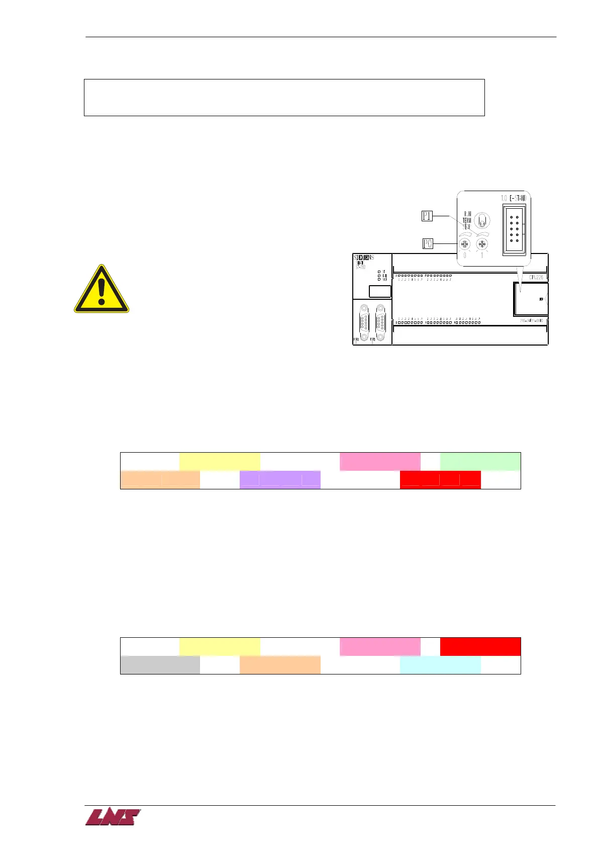
3.2 P0 & P1 Setting
There are two analog settings that can be adjusted
with a screwdriver on the PLC CPU226 (located in the
el. cabinet). The current settings are displayed in
manual mode.
P0 and P1 should only be set by
experienced technicians or authorized
personnel only!
P0: Pushing force override. The pushing force is
automatically adjusted according to parameters F1
and F3. This value can be overridden by the analog
setting of P0. The range is ± 30%. The P0 region (read only) displays the current override percentage
(e.g. 23%).
P1: This setting only applies for fixed headstock lathes. On fixed headstock type lathes the bar feeder
feeds the bar against a turret stop. Before the bar hits the turret stop the speed is reduced. The speed is
changed at distance ‘L’ from the turret stop. The value ‘L’ can be set by P1. The range is from 0 to 51mm.
The current value is displayed in the P1 region.
P 0 =
P0 Region
P 1
= P1 Region
% S
% t
3.3 Message Display
Unless an alarm occurs the ‘Manual’ or ‘Auto’ screen is displayed.
After pressing a function key (F1 – F8) the display will automatically return to the ‘Manual’ screen after
1min.
3.4 MANUAL mode display
P 0 =
P0 Region
P 1 =
P1 Region
Pusher Region
Seq. Region
Speed Region
% S
Torque Region
% t
Seq. Region --- PLC software status (for technician only). – Sequence number
Speed Region --- Motor speed percentage.
Torque Region --- Motor torque percentage.
Pusher Region --- Current pusher position
P0 Region --- see chapter 8 4.2
P1 Region --- see chapter 8 4.2
 Loading...