- 28 -
- :
- : no parity (default).
- : even parity.
- : odd parity.
- : stop bit (1 – 2; default: 1).
- : stability character ( – ; default: ); to be set when the
transmission protocol is selected in mode (see section CONTINUOUS FAST
WEIGHT TRANSMISSION PROTOCOL in Communication protocols manual).
- : number of copies(1 – 9; default: 1).
- : number of blank lines between one printout and the next.
- : printing of custom heading from PC ( – ; default: ).
- : connected printer type:
-
-
-
For more information about protocols and methods of communication, request the
proper manual to technical assistance.
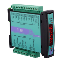
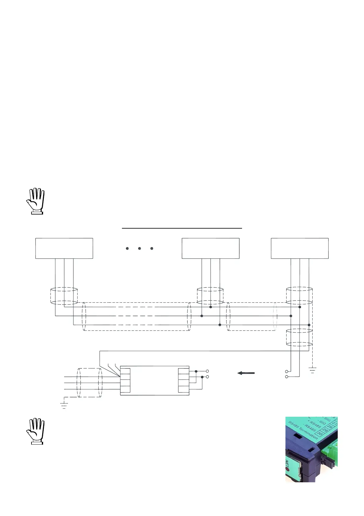
RS485 SERIAL COMMUNICATION
If the RS485 network exceeds 100 metres in length or baud-rate
over 9600 are used, two terminating resistors are needed at the
ends of the network: close the two jumpers indicated in the
picture on the furthest instruments. Should there be different
instruments or converters, refer to the specific manuals to
determine whether it is necessary to connect the above-
mentioned resistors.
INSTRUMENT
RS485 +
RS485 -
max 500 m
RS485 +
3 2 5
PC RS232
RX+
RX-
TX-
TX+
CONVLAU
24 VDC
+
-
0
TX
RX
VIN
RS485 +
RS485 -
RS485 -
RS485 +
RS485 -
RS485 +
RS485 -
GND
GND
GND
INSTRUMENT INSTRUMENT