3 Troubleshooting (continued)
Service Manual
55
Combustion Analysis Procedure
1. Turn the main power off to the boiler by placing
the “On/Off” switch in the OFF position.
2. Remove the fitting from the flue collector.
Note: Combustion measurements will be
made at this point.
3. Insert the probe from a combustion analyzer
into the hole left by the removal of the fitting.
4. Turn the main power on to the boiler by placing
the “On/Off” switch in the ON position.
5. Navigate to the Setup Screen from the Home
Screen by pressing the SETUP button along
the left side of the screen. Enter the installer
password.
6. Select the Service Maintenance Screen. The
tabs will scroll (up and down) to reveal more
options.
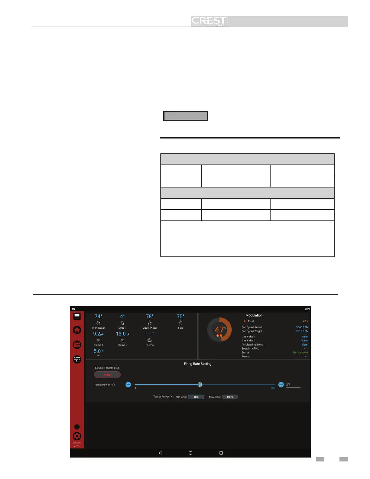
On the Service Maintenance Screen place
heater into Service Mode by selecting the
START button, then selecting the low fire
modulation point (FIG. 3-2).
7. Once the boiler has modulated to rate, measure
the combustion. The values should be near the
target listed in Table 3H (this page). CO levels
should be less than 200 ppm for a properly
installed unit. If the combustion is not near the
target, reference the Troubleshooting Chart for
possible causes and corrective actions.
Table 3H Flue Products
Figure 3-2 Service Screen
You must replace the fitting to prevent flue gas spillage
into the room. Failure to comply could result in severe
personal injury, death, or substantial property damage.
⚠ WARNING
8. Once the heater analysis is complete, test the safety shutoff device by
turning the manual shutoff valve to the OFF position and ensuring the
heater shuts down and registers an alarm. Open the manual shutoff
valve and reset the control.
9. Turn the main power off to the boiler and replace the fitting into the
flue pipe connection.
10. Ensure the boiler is placed back into normal operation.
Natural Gas
Units
*Co๙ (Flue Port)
*O
๙
(Sensor)
ALL 9.5 3.6
Propane
Units
*Co๙ (Flue Port)
*O
๙
(Sensor)
ALL 10.5 4.4
*NOTE: The Hellcat Combustion System is designed to maintain
constant combustion. CO is the target combustion measured from the
flue measurement port. O is the target measurement of the active O
sensor in the combustion chamber. An O2 measurement from the flue
will vary from the O measured in the combustion chamber.
 Loading...