Assembly: log bed
(8) Place the plastic slide rail on
the log bed. Fit the longer (A)
scale against the plastic rail on
the right log bed and the shorter
(B) against the side of the left
log bed. Do not tighten the bolts
all the way. (2 x M6x30 allen
head bolts, 2 x M6 collar nuts)
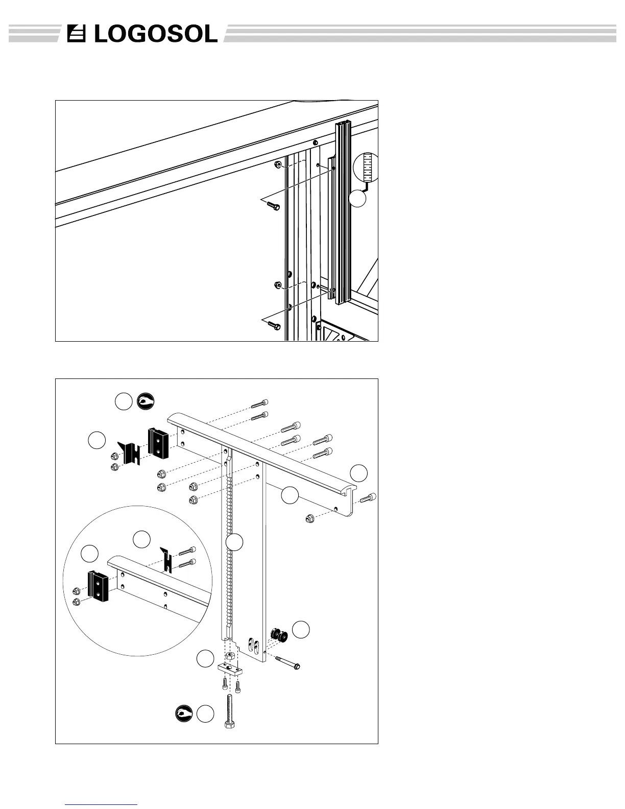
(9) Fit the ratchet bar stop plate
under the lifting beam. (2 x
M6x25 allen head bolts)
(10) Fit the line pulleys. (1 x
M6x60 self-tapping bolt) Apply
some pressure while driving it
in.
(11) Fit the log support on the
lifting beam. As the bolts will be
hard to screw through the holes,
use an Allen wrench to pull the
log support down to the lifting
beam. After app. 20 hours of
use, these bolts will need to
be retightened. (4 x M8x30
self-tapping allen head bolts, 4 x
M8 collar nuts)
(C) Fit the bolt for extra support
(M8x16 allen head bolt, 1xM8
collar nut)
(12) Fit the rachet bar by
threading the adjustment bolt
(D) through the ratchet bar stop
plate and screwing on the nut.
Do not tighten. Place the bar in
the track of the lifting beam and
tighten the adjusting nut on the
bar. (1 x M10x40 bolt, 1 x M10
nut)
Assembly: log side-rest
(7) Fit the log side-rest. make
sure that the measuring scales
are both facing in torwards the
center of the mill so that
operator can read both scales
from the center position.(2 x
M6x20 bolts, 2 x M6 collar nuts)
12
7
A
11
12
B
C
10
8
8
9
D