18
A
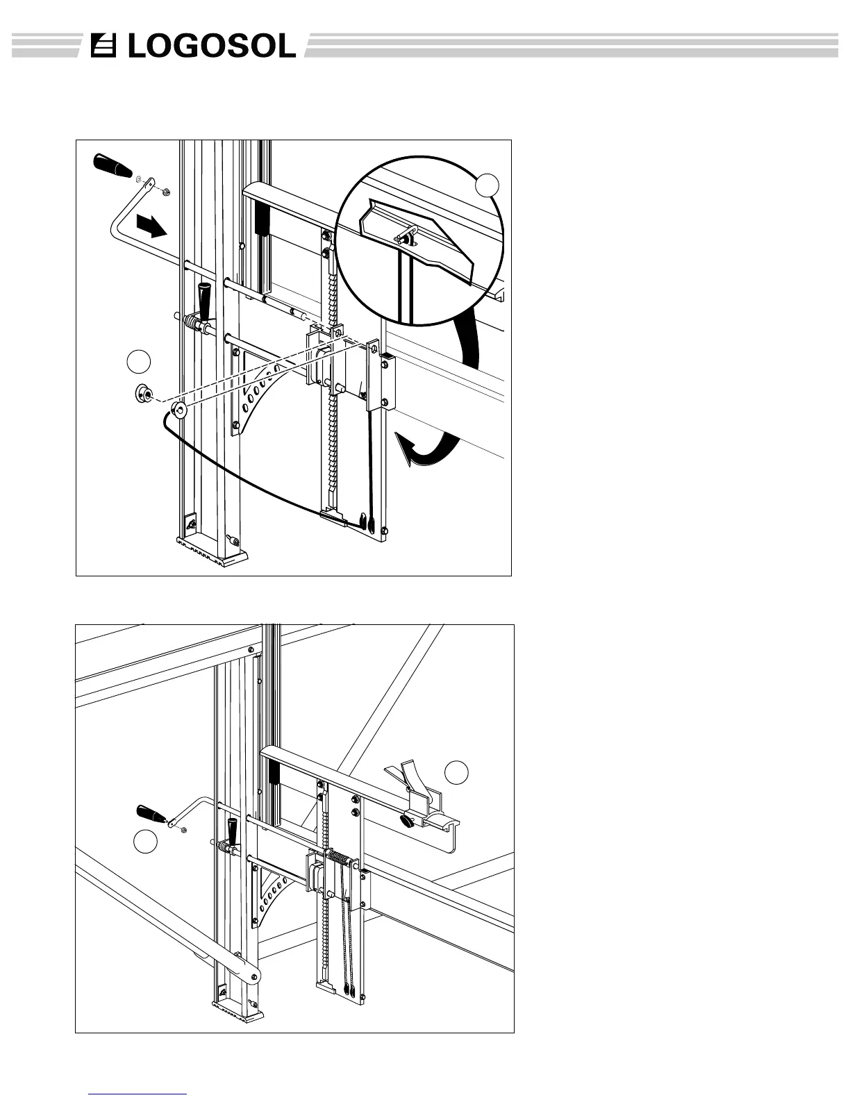
17
A
Assembly: edge support
(18) Slide the edge support onto
the log bed.
(A) Attach crank handle to the
crank rod. Insert an allen
wrench into the end of the
threads on the handle and tight
it with an m8 locking nut.
14
(17) Thread the lifting line under
the outside pulley on the lifting
beam, straight up and around
the pulley on the cross beam
(A) and then down again to the
inner pulley on the lifting beam.
Fit the crank rod through the
upper hole in the long leg and
through the bushing on the
middle flange.
Place the lifting line in the
locking collar recess. Thread
the collar bushing with the line
and the other collar bushing, on
the crank rod.(collars facing out)
Push the crank rod through until
app. 1/8” extends beyond the
outer saddle plate bushing.
Screw the locking screw
(M6x8)on the locking collars into
the recesses on the crank rod.
Then tighten the locking screw
(M8x8) that’s holding the lifting
line.
Assembly: crank and lifting cable