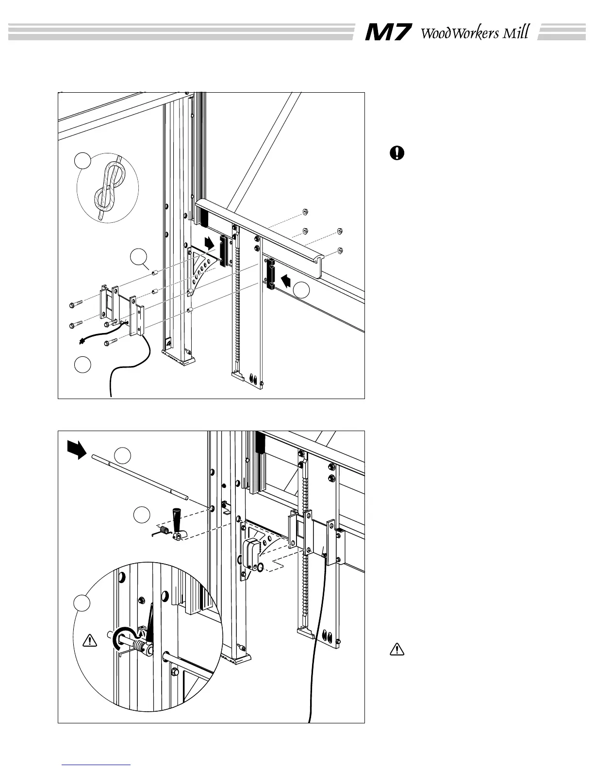
(15) The ends of the ratchet
cam axle are different. Insert
the one that has the recess
nearest the tip through the lower
hole in the long leg.
(16) Thread the short end of the
spring through the scale
selector’s spring holder and slip
both over the cam axle inside
the long leg.
Now thread the axle through the
first flange of the sadle plate.
Thread the ratchet cam on in
front of the opening in the sadle
plate, placing an O-ring on both
sides. Turn the axle so that the
cam locking screw (M6x10)
lines up with the recess. Screw
the locking screw into the
recess.
Screw the cam axle handle
locking screw (M6x10) in the
other recess.
Use protective gloves for
the following steps (B): Pull
the long end of the spring aro-
und to fasten it in the spring
holder on the scale selector
fitting.
Assembly: saddle plate
(13) Thread the lifting line
through the hole in the lower
part of the saddle plate and
make the knot shown (A).
Leave a 1 cm (3/8”) end
after the knot.
(14) Press the steel sleeves into
the holes in the plastic glides.
Place the plastic glides (B) on
each side of the lifting beam and
fit the saddle plate over these.
(4 x M6x40 collar bolts, 4 x M6
collar nuts)
Assembly: rachet mechanism
13
13
A
14
B
15
16
B