
R
Robin SalazarAug 17, 2025
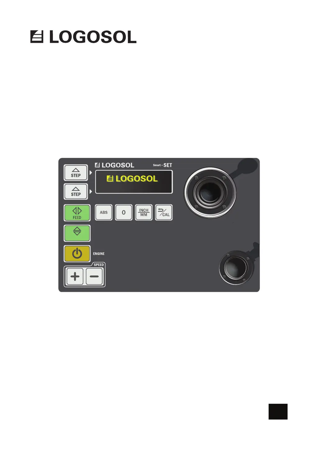
Why does my Logosol Saw Smart Set lose contact with the motor?
- FfitzgeraldoliviaAug 17, 2025
The Smart Set may lose contact with the FEED or UP/DOWN motor due to low battery voltage. Try charging or replacing the battery. If the issue persists, inspect the cables, referring to separate instructions for guidance.


