
J
Jeanette RobinsonSep 13, 2025
What does 'Up to End' mean on the Logosol SMART SET Saw display?
- AAshley HarrisSep 13, 2025
The message 'Up to End' on the display indicates that the STEP function is reaching outside the sawhead’s motion range.
What does 'Up to End' mean on the Logosol SMART SET Saw display?
The message 'Up to End' on the display indicates that the STEP function is reaching outside the sawhead’s motion range.
Explains the meaning of various warning and information symbols used in the manual.
Details safety precautions for the operator, including PPE and personal condition.
Outlines environmental safety requirements like fire extinguishers and first aid.
Specifies critical lubrication points for sawmill longevity and smooth operation.
Guides on checking and calibrating sawhead position before first use.
Instructions for properly storing the control box when not in use.
Defines common fasteners used in machine assembly and maintenance.
Explains how fastener dimensions and lengths are specified and measured.
Lists all parts included in the BOX-MF package.
Lists all parts included in the BOX-M package.
Details parts contained within the BOX-EC package.
Lists components provided in the BOX-CB package.
Enumerate parts included in the BOX-EP package.
Provides a comprehensive list of parts included in the BOX-DV package.
Lists specific parts included in the BOX-TP package.
Lists optional components supplied based on the band sawmill model.
Details parts required for the operation arm assembly.
Details the first step in assembling the BOX-MF and BOX-M units.
Describes the second step for assembling the BOX-MF and BOX-M units.
Outlines the third step in the assembly of BOX-MF and BOX-M.
Details the initial attachment step for the BOX-DV component.
Continues assembly for BOX-DV with the fifth step.
Describes the sixth step in the assembly of the BOX-DV.
Outlines the seventh step for attaching the BOX-DV.
Details mounting the trailer kit on BOX-DV.
Explains proper chain tightening during BOX-DV assembly.
Guides connecting the chain for BOX-DV assembly.
Describes the assembly process for the BOX-EC unit.
Highlights model-specific assembly details for the BOX-DV.
Details routing of cables during BOX-DV assembly.
Explains how to attach the hose in the BOX-DV assembly.
Stresses the importance of correct hose length for BOX-DV operation.
Details the attachment of the operation arm.
Lists components relevant to operation arm assembly.
Describes the step for attaching the BOX-CB unit.
Outlines the assembly step for the BOX-EP unit.
Details the connection of the signal cable for BOX-DV.
Covers the final connection steps for the BOX-DV assembly.
Identifies items found in the petrol engine saw pack.
Details the first cable connection procedure.
Describes the second cable connection procedure.
Outlines the third cable connection procedure.
Provides instructions on connecting the machine's battery.
Details attachment steps for the BOX-TP unit.
Guides on mounting the panel for the BOX-TP.
Instructions for installing the control cable for emergency stop and control box.
Explains fuses on the component panel and battery.
Highlights critical warnings before performing throttle adjustment.
Step-by-step guide for adjusting the engine's throttle cable.
Provides a step-by-step guide on starting the machine's engine.
Details correct steps for safely stopping the machine's engine.
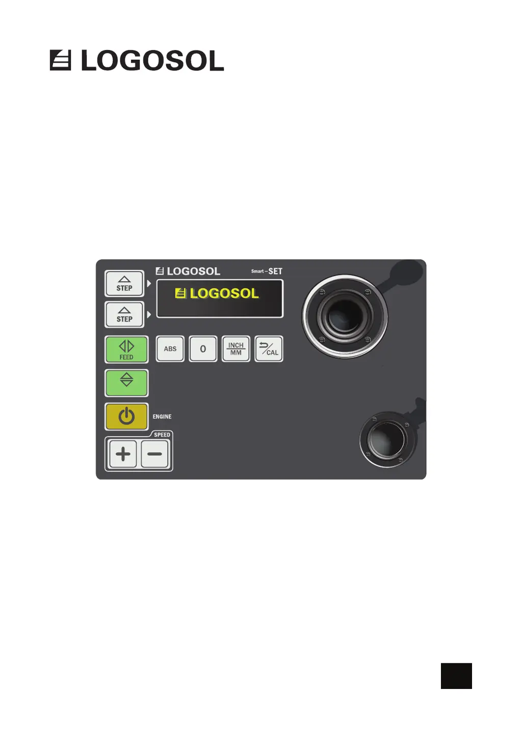
Introduces components of the Logosol Smart Set control unit.
Explains the functionality and progressive nature of the control lever.
Describes the purpose and function of the enabling switch button.
Details functions of various program keys on the control panel.
Explains different settings available on the Smart Set interface.
Outlines the process for calibrating sawhead position for accurate measurements.
Explains how to cancel an operation or return to standby mode.
Provides specific details on enabling switch location and role.
Explains how Step mode allows repeating preset cut values.
Guides on setting a desired value for Step mode.
Describes how to activate and utilize Step mode for cutting.
Instructions on turning off the Smart Set control unit.
Explains the Up/Down key for vertical sawhead movement and position display.
Illustrates a typical workflow for sawing a log using the Smart Set.
Details setting initial sawblade height for making a cut.
General steps for operating functions via the control panel.
Explains using the Feed key and control lever for sawhead movement.
Describes revving up the engine and starting the saw blade.
Describes the Smart Set interface for displaying measurements and units.
Explains how the interface shows distance from log bed to sawblade.
Details how the '0' key sets a zero point for relative measurements.
Guides on switching between inch and millimeter units.


