- 96 -
FOCS Workshop Manual_cod. 1.5302.351_7° ed_ rev. 06
wKhwK/g
205
002215,5381÷291992÷582
006327,7511÷021043÷623
206
002253,7741÷551972÷562
006329,998÷39043÷623
309
002280,1199÷501472÷162
006360,5185÷06243÷823
4021
002287,4157÷97272÷852
006322,0244÷8,54043÷623
T/4021006305,9253÷63092÷482
224
10
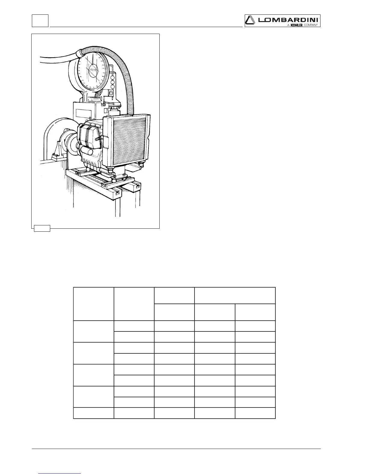
Pump/injector unit delivery setting with braked engine
1)Run the engine to the maximum speed.
2) Screw flow limiter C (see fig. 219).
3) Load the engine up to the power and number of revs required by
the application’s manufacturer.
4) Check that consumption is within the values allowed for in the
settings table (see below).
If consumption is not within the given figures, it is necessary to
change the balance conditions shown to the brake, altering the
load and the speed governor. Redo the consumption check on the
stabilised engine.
5) Unscrew limiter C until the engine rpm start to decrease. Lock the
limiter using the lock nut.
6) Completely release the brake and check the rpm at which the
engine stabilises.
The performance of the speed governor must meet the class
required by the application’s manufacturer.
7) Stop the engine.
8) Recheck the valve clearance with the engine cold.
Specific fuel consumption
Time (sec) per
100 cm
3
Power*
( NB curve )
RpmEngine
Required settings (as most commonly applies)
* Refers to power curve NB, see pages 18÷20 and after run-in.
Settings
 Loading...


