Fig.
14-
High
Response
Adjustment
Upper
Link
The
sway chains are used to limit the lateral
or
trans-
verse
movement of the implement. They are adjusted
by
rotating the adjusting sleeves like a turnbuckle.
During
transport of any type of implement, the chains
should
be tightened to hold the implement stationary.
When
working with implements such as graders, roll-
ers,
scrapers, mowers, weeders, spreader, drills, plant-
ers,
etc. the chains should be tight.
When
working with implements such as plows, disc
harrows, cultivators, ditch diggers, etc., leave a little
slack
in
the chains
Refer
to the "Guide To Hydraulic Lift Control" for further
information.
The
tractor is shipped from the factory set
up
for a
Category 1 three point hitch. The factory hitch has
holes
for 7/8" (22.2mm) pins in the lower links and
an
upper link with a 3/4" (19.1 mm) hole and pin. Also, the
tractor
is
shipped with an extra upper link end with a 1"
(25
.4mm) hole and pin, and two bushings for the lower
links,
so
that the hitch can be converted to Category
II.
To
convert to a Cat.
II
three point hitch, use the
following procedure:
1.
Remove the sway chain eye bolts from the lower
draft arms and remove the pin from the lower clevis
of
each lift link.
2.
Remove the larger snap pins holding the front ends
of the lower draft arms on the hitch pins under the
tractor differential. Slide the arms off the pins.
Remove the bushings located on each pin ( or
in
the draft arm hole), and store in the tool box.
3.
Tum each lower draft arm end over end and then
rotate 1/2 a
tum
to place the end with the 1 1/8"
16
(28.6mm) holes away from the rear of the tractor.
Slide the end of the arm with the 7/8" (22.2mm)
hole back onto the pins
under
the tractor differen-
tial. Then replace the snap pins.
er
Hitch Point
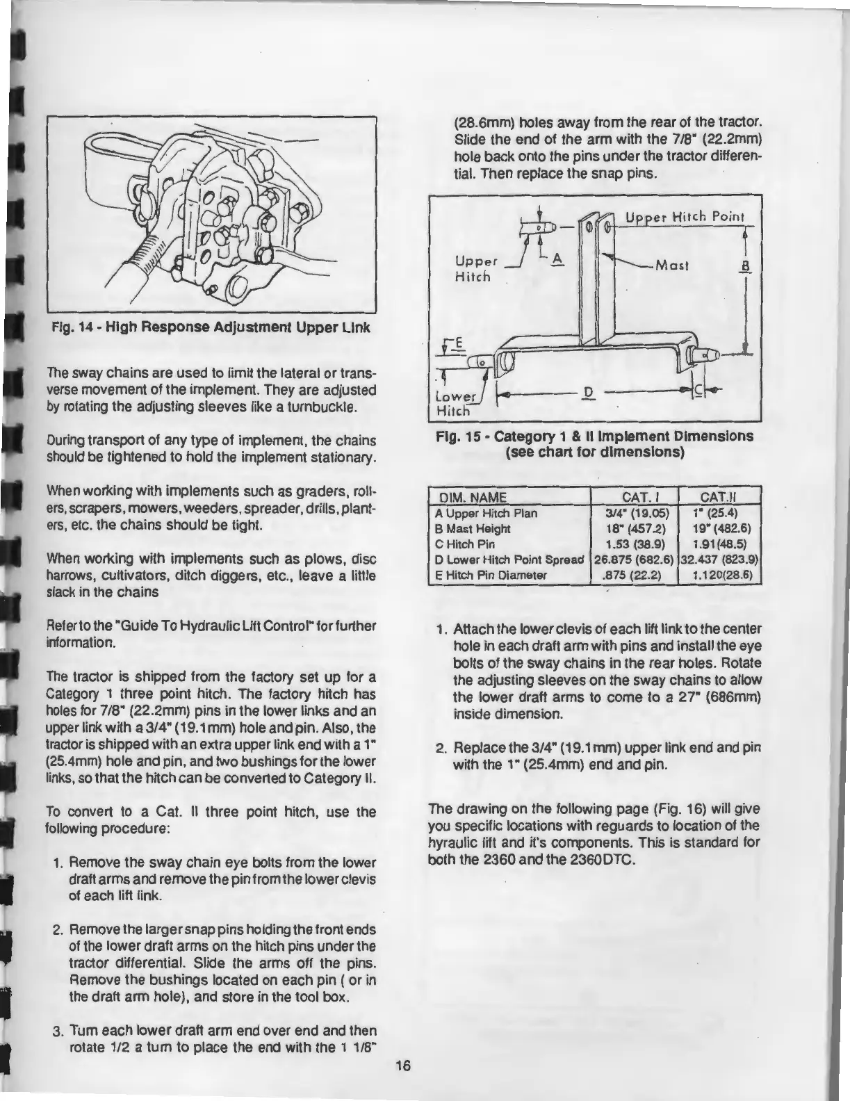
Fig.
15-
Category
1 & II
Implement
Dimensions
(see
chart
for
dimensions)
DIM. NAME CAT. I
CAT
.
II
A Upper Hitch Plan 3/4" (19.05)
1" (25.4)
B Mast Height 18" (457.2)
19" (482.6)
C Hitch Pin 1.53 (38.9)
1.91(48.5)
D Lower Hitch Point Spread 26.875 (682.6)
32.437 (823.9)
E Hitch Pin Diameter .875 (22.2)
1.120(28.6)
1.
Attach the lower clevis of each lift link to the center
hole in each draft arm with pins and install the eye
bolts of the sway chains in the rear holes. Rotate
the adjusting sleeves
on
the sway chains to allow
the lower draft arms to come to a
27"
(686mm)
inside dimension.
2.
Replace the 3/4" (19.1 mm) upper link end and pin
with the 1" (25.4mm) end and pin.
The drawing on the following page (Fig. 16) will give
you specific locations with reguards to location of the
hyraulic lift and it's components. This is standard for
both the 2360 and the 2360DTC.