Switch Postion
Circuit
3
0
1 2
Themostarter
X X
Starter
X
X
"X"
Indicates
that
the
circuit
Is
energized
7.
Work
Llg
ht
Indicator-
The indicator
is
a blue lamp
which burns when the ignition switch
is
in position
"3" and indicates that the front work lights are on.
8.
Alternator
Warning
Lamp
- This red lamp indi-
cates a faulty operation of the battery charging
system. The lamp should come on when the igni-
tion switch is turned on. If it does not, check the
fuse and bulb. Once the engine is started, the lamp
should go out.
If
it does not, stop the engine and
check the voltage regulator, battery charge control
relay,
or
for loose wires.
9. Oil
Pressure
Warning
Lamp
- This red lamp
indicates insufficient engine oil pressure. The lamp
should come on when the ignition switch
is
turned
on.
If
it
does not, check the fuse and bulb. The lamp
should go out a few seconds after the engine has
been started.
If
it stays on or comes on any time
while the engine is running, stop the engine imme-
diately and find and correct the cause.
1
o.
Turn
Signal
Indicators-
These indicato.rs are two
green lamps which blink
~h~n
the
tur.n
s1gnals
are
activated. The right lamp
1nd1cates
a nght turn,
~nd
the left lamp indicates a left turn. If the lamps
fa1l
to
blink, find and correct the cause as soon
as
pos-
sible.
11
. Parking
Brake
Warning
Lamp
- This lamp is
currently not used.
12.
Turn
Signal
Switch
- This switch controls .the
operation of the turn signal lights. Rotate the
sw1tch
handle clockwise to signal for a right turn, and
counterclockwise to signal a left turn. Rotate the
switch either direction to the center position to turn
off the signal lights.
13. 4-Way
Flasher
Switch
- This
swit~h
controls .the
4-Way (Hazard) flasher lights.
Pull1ng
the
sw1tch
out turns on the flashers and pushing
it
back in
turns them off. The turn Signals will operate with
the 4-Way flashers operating.
14. Flasher Fuse - This fuse
is
used for the
4-W<:-Y
flashers and turn signals. To remove the fuse,
tw1st
the knob counterclockwise and then pull the knob
out.
OPERATIONS
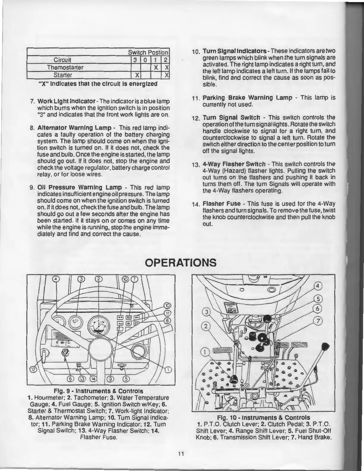
Fig.
9-
Instruments
&
Controls
1. Hourmeter; 2. Tachometer; 3. Water Temperature
Gauge;
4.
Fuel Gauge; 5. Ignition
Swi~ch
w/K~y;
6.
Starter & Thermostat Switch; 7. Work-light Indicator;
8. Alternator Warning Lamp; 10. Turn Signal Indica-
tor; 11. Parking Brake Warning Indicator; 12. Turn
Signal Switch; 13. 4-Way Flasher Switch; 14.
Flasher Fuse.
11
Fig.
10-
Instruments
&
Controls
1. P.T.O. Clutch Lever; 2. Clutch Pedal; 3. P.T.O.
Shift Lever; 4. Range Shift Lever;
5. Fuel Shut-Off
Knob;
6. Transmission Shift Lever; 7. Hand Brake.