2. Full Float - This position is used for implements
that rest indirectly on the ground via Gauge wheels,
skids,
or
other means when operating.
To use the full float position:
A. Set the controls for position control.
B. Move the controlleverto its' lowest position (See
Fig. 18)
3.
Draft Control - In this position the upper link
sensing system is activated to automatically vary
the height of the implement to maintain approxi-
mately the same draft (pull) at all times.
To place the lift in the draft control mode:
A.
Raise the implement to full transport height by
raising the control lever completely.
B.
Move the mode lever upward.
C. Rotate the upper link anchor support wedge
up
and to the right to disengage
it
from the anchor
and chassis, to allow the anchor full freedom of
movement for draft sensing.
D. At the start of operation lower the controlleverto
move the implement from the transport position
on to the ground. The farther the control lever is
lowered, the deeper the implement will pen-
etrate the ground, and the higher the draft will be.
When the desired depth,
or
draft, has been met,
move the control lever stop against the control
lever so that the same operating position can be
returned to after raising the lift for turns
or
trans-
port.
E.
After the operating height has been selected,
while the implement is still working, adjust the
sensitivity lever forward to obtain maximum re-
sponsiveness to draft changes without unneces-
sary movement,
or
"hunting"
of
the lift. (See Fig.
18)
F.
In cases where large variations
in
the soil condi-
tions are present and cause undesirable depth
variations from the draft control system, the
desired working depth can be maintained (within
the tractive capabilities of the tractor) by adjust-
ing the control lever as soil conditions change.
NOTE: Always raise the hydraulic lift to its high-
est position before changing the lift position to
draft control,
or
vice versa. Failure to do so may
cause damage to the lift control mechanism.
18
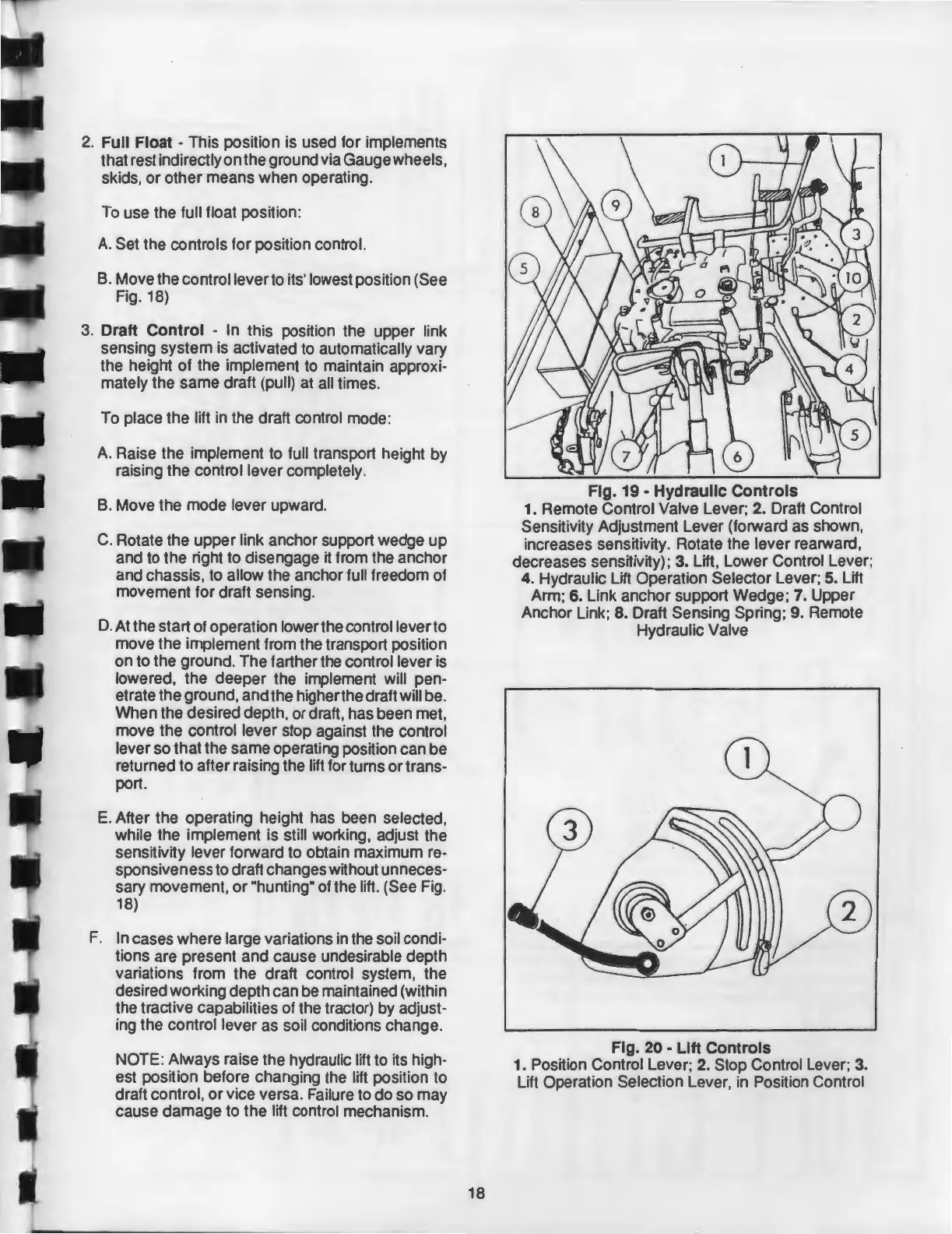
Fig.
19-
Hydraulic Controls
1. Remote Control Valve Lever; 2. Draft Control
Sensitivity Adjustment Lever (forward as shown,
increases sensitivity. Rotate the lever rearward,
decreases sensitivity);
3. Lift, Lower Control Lever;
4. Hydraulic Lift Operation Selector Lever; 5. Lift
Arm;
6. Link anchor support Wedge; 7. Upper
Anchor Link;
8. Draft Sensing Spring; 9. Remote
Hydraulic Valve
Fig. 20 - Lift Controls
1.
Position Control Lever; 2. Stop Control Lever; 3.
Lift Operation Selection Lever, in Position Control