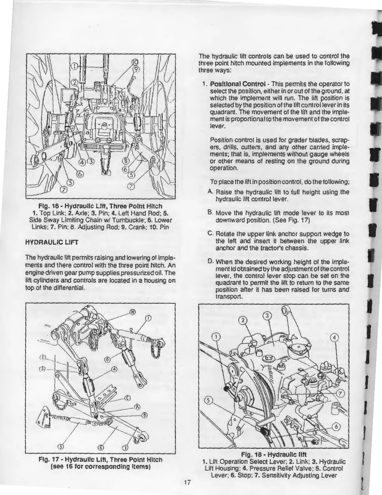
Fig.
16
·Hydraulic
Lift, Three
Point
Hitch
1. Top Link;
2.
Axle; 3. Pin; 4. Left Hand Rod; 5.
Side Sway Limiting Chain w/ Turnbuckle; 6. Lower
Links; 7. Pin; 8. Adjusting Rod; 9. Crank; 10. Pin
HYDRAULIC LIFT
The hydraulic lift permits raising and lowering of imple-
ments and there control with the three point hitch. An
engine driven gear pump supplies pressurized oil. The
lift cylinders and controls are located in a housing on
top of the differential.
Fig. 17 •
Hydraulic
Lift, Three
Point
Hitch
(see
16
for
corresponding
Items)
17
The hydraulic lift controls can be used to control the
three point hitch mounted implements in the following
three ways:
1.
Positional
Control
- This permits the operator to
select the position, either in or out of the ground,
at
which the implement will run. The lift position
is
selected by the position of the lift control lever in its
quadrant. The movement of the lift and the imple-
ment
is
proportional to the movement
of
the control
lever.
Position control is used for grader blades, scrap-
ers, drills, cutters, and any other carried imple-
ments; that is, implements without gauge wheels
or other means of resting on the ground during
operation.
To
place the lift in position control, do the following;
A. Raise the hydraulic lift to full height using the
hydraulic lift control lever.
B.
Move the hydraulic lift mode lever to its most
downward position. (See Fig. 17)
C. Rotate the upper link anchor support wedge to
the left and insert it between the upper link
anchor and the tractor's chassis.
D.
When the desired working height of the imple-
ment id obtained by the adjustment
of
the control
lever, the control lever stop can be set on the
quadrant to permit the lift to return to the same
position after
it
has been raised for turns and
transport.
Fig. 18
·Hydraulic
lift
1. Lift Operation Select Lever;
2.
Link; 3. Hydraulic
Lift Housing;
4.
Pressure Relief Valve;
5.
Control
Lever;
6.
Stop; 7. Sensitivity Adjusting Lever
f
I
J
r
r