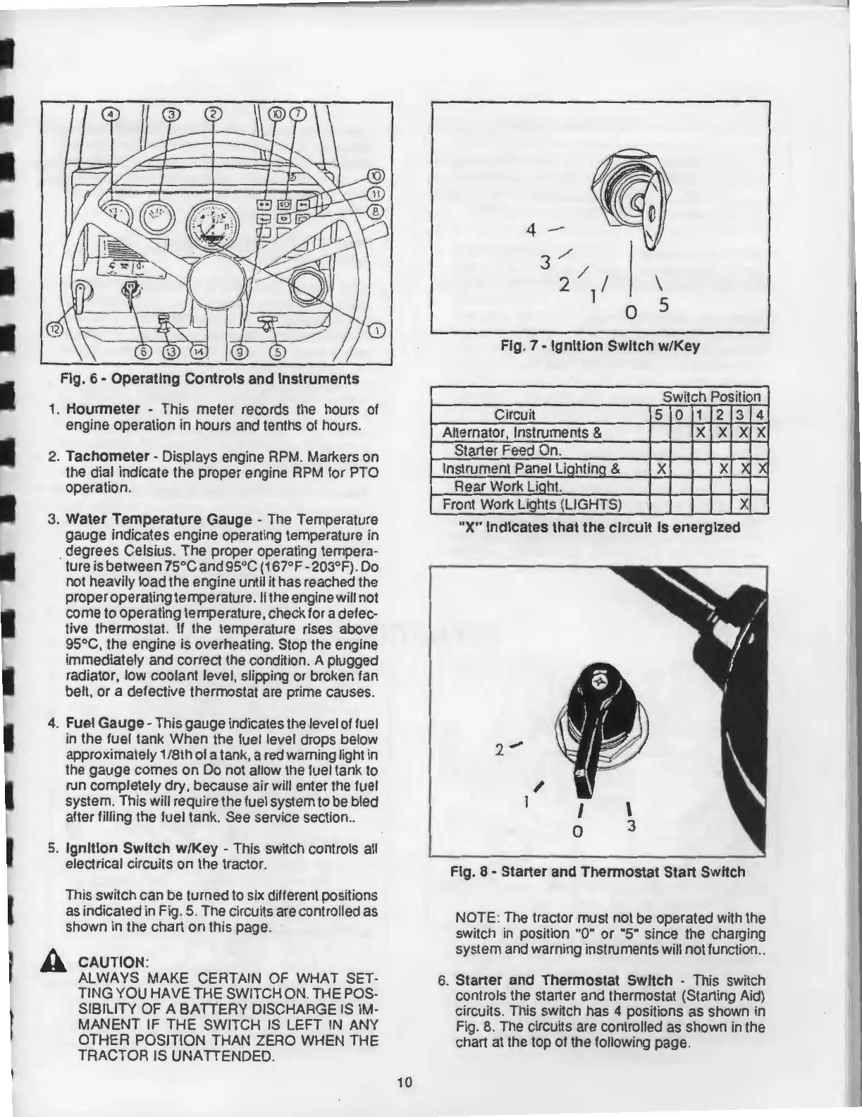
Fig.
6-
Operating
Controls
and
Instruments
1.
Hourmeter
- This meter records the hours of
engine operation in hours and tenths of hours.
2.
Tachometer-
Displays engine RPM. Markers on
the dial indicate the proper engine RPM for PTO
operation.
3.
Water
Temperature
Gauge
- The Temperature
gauge indicates engine operating temperature in
. degrees Celsius. The proper operating tempera-
ture is between 75°C and 95°C ( 167°F-203°F). Do
not heavily load the engine until
it
has reached the
proper
operating temperature. If the engine will not
come to operating temperature, check for a defec-
tive thermostat. If the temperature rises above
95°C, the engine is overheating. Stop the engine
immediately and correct the condition. A plugged
radiator, low coolant level, slipping or broken fan
belt,
or
a defective thermostat are prime causes.
4. Fuel
Gauge-
This gauge indicates the level of fuel
in the fuel tank When the fuel level drops below
approximately 1 /8th of a tank, a red warning light in
the gauge comes on Do not allow the fuel tank to
run completely dry, because air will enter the fuel
system. This will require the fuel system to
be
bled
after filling the fuel tank. See service section
..
5.
Ignition
Switch
w/Key
- This switch controls all
electrical circuits
on
the tractor.
This switch can be turned to six different positions
as indicated in Fig.
5.
The circuits are controlled as
shown in the chart on this page.
CAUTION:
ALWAYS
MAKE
CERTAIN OF WHAT SET-
TING YOU
HAVE
THE
SWITCH ON. THE POS-
SIBILITY
OF
A
BATTERY
DISCHARGE IS IM-
MANENT
IF
THE
SWITCH
IS
LEFT
IN
ANY
OTHER POSITION THAN ZERO WHEN THE
TRACTOR IS UNATTENDED.
10
4 -
3 /
2/
I
1
0
\
5
Fig.
7-
Ignition
Switch
w/Key
Switch Position
Circuit
5
0
1 2
3
4
Alternator, Instruments &
X X X X
Starter Feed On.
Instrument Panel Liahtina
& X
X
)(
Rear Work Liaht.
Front Work Lights (LIGHTS)
X
"X"
Indicates
that
the
circuit
Is
energized
/
1
I
0
Fig.
8-
Starter
and
Thermostat
Start
Switch
X
NOTE: The tractor must not be operated with the
switch
in
position "0"
or
"5" since the charging
system and warning instruments will not function
..
6.
Starter
and
Thermostat
Switch
- This switch
controls the starter and thermostat (Starting Aid)
circuits. This switch has
4 positions as shown in
Fig. 8. The circuits are controlled as shown in the
chart at the top of the following page.