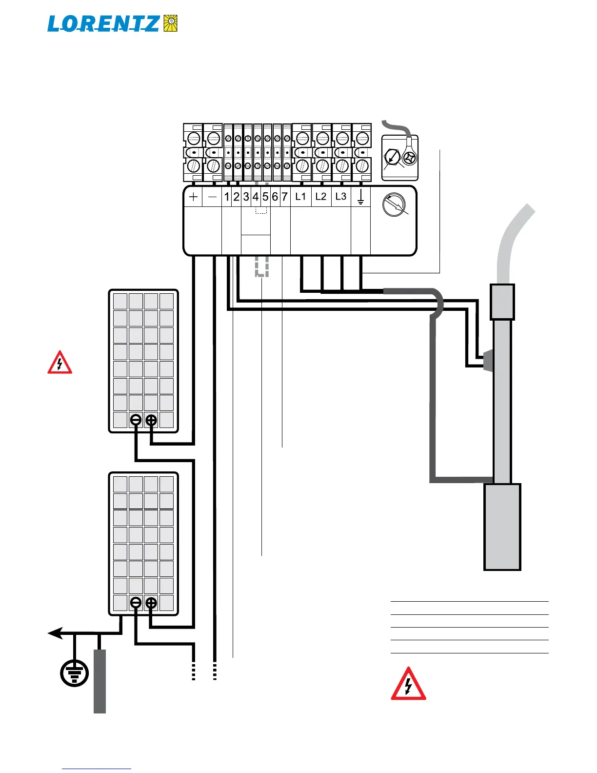
PV arrays in series:
2 to 8 panels
(see accepted open-
circuit voltage below)
earth
ground
to any ground ter-
minal at controller
pump
motor
low water
level probe
NO BATTERY JUMPER
In solar direct operation, no jumper must be
installed between terminals 6 and 7.
L1/L2/L3 must match the numbers on
pump leads. Other combinations may
cause reverse rotation! For wire size,
please refer to sizing table.
water pipe to
distribution
system
FLOAT SWITCH
A float switch kit makes contact when water level
in a tank rises to stop the pump. Connect termi-
nals 3 (NO) and 4 (COM) to the float switch and
connect terminals 4 and 5 with jumper wire.
If you are not using a float switch, install a
jumper between terminals 4 and 5.
LOW WATER PROBE
If you are not using a low water probe, install a
jumper between terminals 1 and 2.
Max open-circuit voltage for PV modulesTable 12:
PS200 100 V DC
PS600 150 V DC
PS1200 200 V DC
PS1800 200 V DC
WARNING No disconnect switches
may be installed in power wires
between motor and pump controller!
The connection of the motor cable to
switched-on controller might cause irreparable
damages which are excluded from warranty!
Test max. open-
circuit voltage!
See allowed
max. open-circuit
voltages for dif-
ferent systems
below.
This is an example, using 2 – 8 × 12 V
nominal PV modules. Your system may vary
in the number, voltage, and configuration
of PV modules. The system here below is
typical for either PS200 (2 – 4 modules in
series), PS600 (4 – 6 modules in series),
PS1200 (6 – 8 modules in series) or PS1800
(6 – 8 modules in series).