tor speed (RPM) is proportional to the AC frequency. The
frequency starts low (about 20 Hz), and increases gradually
to a maximum of 3,400 RPM (70 Hz).
The float switch circuit operates at 12 V DC, carrying
maximum current of 4.7 mA. The controller has terminals
for either normally open (N.O.) or normally closed (N.C.)
switching.
The low-water probe circuit applies 5 V DC to a probe. The
water conducts a small amount of current between the two
electrodes of the probe. If the probe is out of the water, the
controller stops the pump. When the water level recovers,
there is a 20 minute delay before restart.
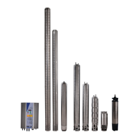
Pump end – centrifugal models Pumps with a MODEL
NUMBER CONTAINING “C” use a multi-stage centrifugal
pump end, similar to that of conventional well pumps –
this is for high volume at 75 ft (23 m) or less.
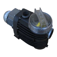
Pump end – helical rotor models Pumps with a
MODEL NUMBER THAT DOES NOT CONTAIN “C” have a
helical rotor pump end (also called “progressive cavity”
pump). The rotor fits closely into a rubber stator that has a
helical groove of a different pitch. The mismatch between
the rotor and stator forms sealed cavities that trap water.
As the rotor turns, the cavities progress toward the outlet.
Reference Section12
Solar array Photovoltaic (PV) cells produce electricity di-
rectly from sunlight (not from heat). Light causes electrons
to jump from the top layer of the cell, into “holes” in the
layer underneath. When a circuit is made between top and
bottom layers, electric current flows. Each cell produces
about ½ V. As sunlight varies, the current (amps) varies
while the voltage stays nearly constant.
PV cells are connected in series for the desired voltage, and
sealed under glass to make a “PV module”.The assembly
of modules is called a “PV array”. There are no moving or
wearing parts in PV modules. The glass used in high quality
PV modules is tempered, and is extremely strong. It is
tested to federal standards that include resistance to a 1 in
ice ball traveling at 100 mi per hour.
Some PS pump systems use a “passive” or active solar
tracker, which tilts the array to follow the sun through the
day. Daily output can be increased by that feature up to
50 %.
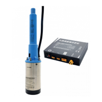
Brushless motor system PS pumps use a “brushless
DC motor system”. This consists of a special 3-phase AC
motor (synchronous, permanent magnet), and a controller
that changes the solar DC power to 3-phase AC. AC creates
a rotating magnetic field that causes the shaft to spin. The
motor’s speed is determined by the frequency of the AC
power. The controller varies the frequency (and the voltage)
to bring the motor up to speed slowly. It then adjusts the
motor speed according to the power available from the
sun.
Principles of Operation12.1
Older-technology solar pumps have a traditional DC motor
that uses “brushes” (small blocks of carbon-graphite) to
conduct current to the spinning part of the motor. Not only
do the brushes wear out in a few years, but it is necessary
to have air in the motor and a perfect seal to keep water
out. The brushless motor is filled with, and lubricated
by water. It is similar mechanically to conventional AC
submersible motors.
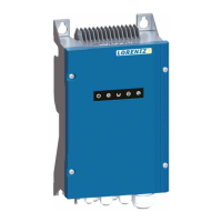
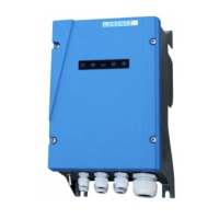
Controller The PS-controller starts the pump slowly and
adjusts its speed according to the pumping load and the
power available from the solar array. Power output from
the array is optimally matched to the load by maximum
power point tracker (MPPT) and linear current
booster (LCB) functions, to produce maximum power
transfer throughout all conditions. The LCB function is
analogous to an automatic transmission in an automobile.
It starts the pump in “low gear” (it lowers the array voltage
and boosts the current). Under low sun conditions, it stays
in “low gear” to resist stalling. As sunlight increases, it
advances continuously toward “high gear” (higher volt-
age). The MPPT system refines the LCB function by tracking
changes in the array voltage. Array voltage varies primarily
with temperature (it is higher at low temperatures). When
the pump stalls in low sunlight, the controller switches the
pump off.
The controller converts the DC power from the solar array
to 3-phase AC power to run the motor. Due to the special
natuerl of this AC voltage which is made with PWM
technology it cannot be measured with a multimeter. Mo-
 Loading...


