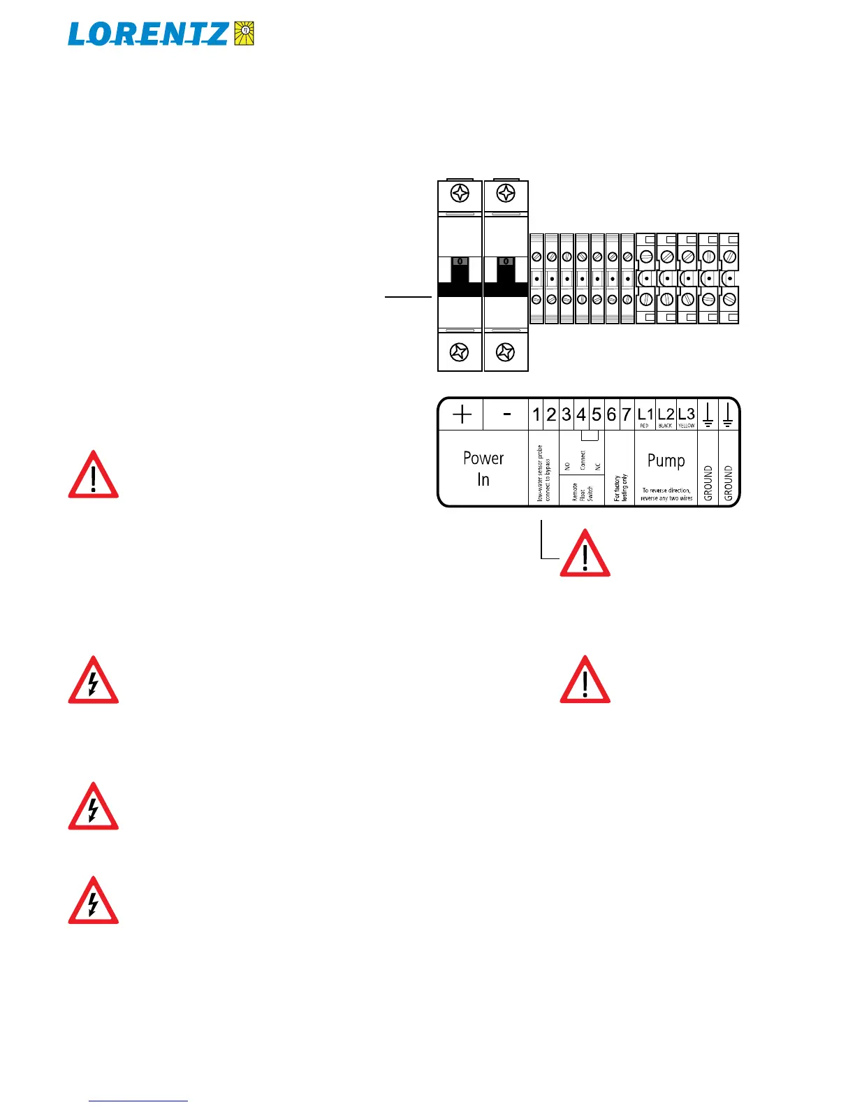
CAUTION If you are not using a low-
water probe, connect a small wire
between terminals 1 and 2.
CAUTION Loose connections are a
comon cause of failure. Pull each con-
nection to confirm.
4.4 Solar Array Disconnect Switch in the Junction Box
Junction Box (Controller Input) Wiring4.5
WARNING TEST THE VOLTAGE before
connecting power to the controller.
Voltage (open circuit) must not ex-
ceed 100 V for PS200, 150 V for PS600
and 200 V for PS1200 systems. (Even
in cloudy weather, the open circuit
voltage will be near maximum.)
WARNING Do not apply a direct
connection or an amp meter between
+ and – when the controller is con-
nected. A short circuit here will cause
a strong discharge.
WARNING SOLAR-DIRECT systems
only — Do not connect any electrical
load to the solar array if it is not part
of the LORENTZ Pump system. Con-
nection of a battery charger, active
solar tracker controller, electric fence
charger, or other load simultane-
ously with LORENTZ PS systems may
“confuse” the controller and prevent
proper operation.
The disconnect switch satisfies National Electrical Code
requirements for a safety disconnect between the solar ar-
ray and the controller. During installation and maintenance,
switch off the disconnect switch to prevent shock and arc
burn hazard.
Note: Overload protection (fuses or circuit breaker) is NOT
required in the solar array circuit.
Explanation:
1. Short circuit current from the solar array can never
reach the ampacity (maximum safe amps capacity) of
the recommended wire.
The PS controller has internal overload protection.2.
disconnect switch
System Diagram For solar-direct systems, refer to the
System Diagram at the end of this manual.
Ground connections The two ground terminals in the
junction box are bonded together and are also bonded to
the metallic enclosures of both the junction box and the
controller. See section 4.2
POWER IN Ensure that the solar array DISCONNECT
SWITCH (or battery fuse or circuit breaker) is OFF. Connect
the power from the solar array to the input terminals in the
junction box. Observe polarity. If your wires are not clearly
marked +/–, test them using a DC voltmeter or multitester.
PUMP See section 4.8.
Low Water Probe See section 4.9
Float Switch See section 4.10, Automatic Control for Full-
Tank Shutoff. A connection is made at the factory between
terminals 4 and 5. If you are NOT using a float switch,
leave this connection in place.
CAUTION If you are not using a low-
water probe, connect a small wire
between terminals 1 and 2.
Figure 6:
Controller terminals
 Loading...


