In-well Assembly and Installation6
Rubber Spacers6.1
This applies ONLY to models HR-07, 10, 14 and 20 (HR-07,
14 and 20 pump ends).
Helical rotor pumps vibrate due to the eccentric rotation of
the helical rotor. This is normal. Rubber spacers reduce the
vibration that may be transferred to the well casing. Models
-03 and -04 vibrate very slightly so they are not supplied
with rubber spacers.
Pump heads with and without rubber Table 2:
spacers
Pump head without
rubber spacer
with
rubber spacer
HR-03
HR-03H
HR-04
HR-04H
HR-07
HR-07H
HR-10
HR-14
HR-14H
HR-20
HR-23
Clearance for drilled well casings Rubber spacers fit a
6 in (150 mm) inside-diameter or larger well casing.
Cut the rubber spacer legs to fit smaller casing If
you are installing the pump in a well casing smaller than
6 in (150 mm), cut the spacer legs. Grooves indicate where
to cut for a 4 in (100 mm) casing. Use a fine-tooth saw to
cut the rubber.
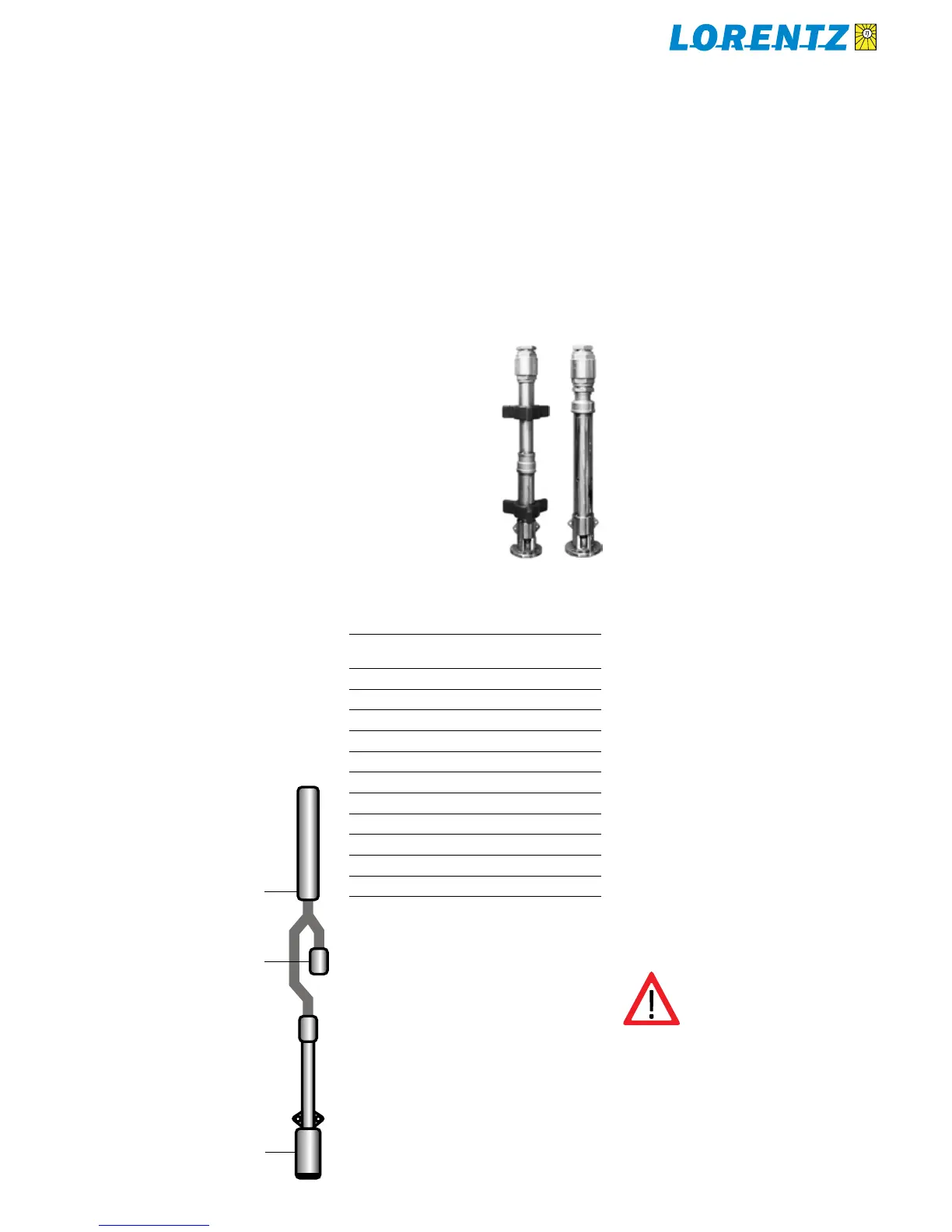
Pump head with Figure 21:
and without rubber spacers
Machine Installation6.2
If you are professionally equipped to install conventional
AC submersible pumps, you can use the same equipment
and methods for our pumps. PS pumps have no special
pipe requirements. You can use any suitable rigid or flexible
pipe. The only exception is to consider reducing the pipe
size in cases of high sand concentration (to increase flow
velocity). See sections 6.3, Drop Pipe, and 13.3, Water Pipe
Sizing Chart
Installing the Pump Under a Windmill or Hand 5.9
Pump Cylinder
PS pumps can be combined with a classic water-pumping
windmill or hand pump, to utilize both energy sources
automatically. The following system is often used with a
conventional AC pump, so a generator can be used for
backup. The AC pump is placed immediately below the
cylinder, and connected to the cylinder’s threaded intake.
When power is applied to the AC pump, it pushes water
up through the cylinder, pushing its valves open. When the
windmill draws water, it sucks it up through the AC pump
with little resistance. (The centrifugal pump end of the
standard AC pump allows water to flow through it when it
is stopped.) When both pumps operate, each one is relieved
of its load, more or less.
This system can be employed with PS pumps. A centrifugal
model (one with a “C” in the model number) will allow
water to flow freely through it and does NOT require any
special precautions. For helical rotor models, the following
warning applies.
To use a helical rotor pump under a cylinder, you must build
a bypass assembly with a T fitting and a foot valve (a check
valve with intake screen). When the cylinder’s flow exceeds
that of the solar pump, water is sucked in through the foot
valve. When the solar pump’s flow exceeds that of the
cylinder, the foot valve closes and allows the solar pump to
work normally and push up through the cylinder.
To make this system for a casing 6 in (150 mm) or smaller,
an offset using 45° elbows must be carefully constructed,
as illustrated. Copper fittings must be used for the bypass
assembly due to the limited space in the well casing. Do
not use any iron fittings in this assembly.
Bypass foot valve assembly Figure 20:
with offset elbows to fit a drilled well
casing
windmill or hand pump cylinder
foot valve
pump
CAUTION The threads in the check
valve require an adhesive sealant.
They are not tapered pipe thread.
Normally, there is no reason to
remove the check valve. If you do remove it, use a
hardening adhesive sealant or epoxy glue when
you replace it. See CAUTION in section 9.1

 Loading...


