4.3 Solar Array Wiring
The solar array can produce hazardous voltage even under
low light exposure. To prevent shock hazard while wiring
the array, leave one or more wires disconnected or cover it
with opaque material.
Solar-direct (non-battery) systems use a variety of array
configurations. Some use 12 V (nominal) modules, and
some use 24 V modules. Modules are connected in series
for 24 – 36 – 48V and up to 96 V (for PS1200 Systems), and
sometimes also in parallel to increase the current. Refer to
the System Wiring Diagram for your system, attached
at the end of this manual. Be sure the modules (panels)
match the description on your System Wiring Diagram.
Solar module connections The terminals in the module
junction boxes can be confusing. Refer to the module
manufacturer’s instructions that are packed with the
modules. Make strong connections that will hold for many
years. Most array failures are caused by loose, corroded, or
shorted connections.
Type of wire Use either electrical conduit or outdoor UV-
resistant wire. The solar array has a life expectancy beyond
twenty years. Don’t degrade it with inferior materials!
Use minimum wire size #12 (4 mm
2
) for the connections
between modules and for short distances to the controller.
Some appropriate types of wire are: USE, UF, SE and SOOW.
Solar tracker wiring If you are installing a solar tracker,
pay careful attention to the wire section that leads from
the moving rack down to the stationary mounting pipe.
Use a highly flexible wiring assembly. Form a drip loop to
shed water and to minimize stress. SEE TRACKER PHOTO
and caption in the PHOTO GALLERY. Secure the assembly
mechanically at each end so the insulation and the con-
nections are not stressed by the tracker’s motion. Swing
the tracker fully in each direction, at various seasonal tilt
angles, to verify that the cable will not rub or restrict the
tracking motion.
MC connectors Some PV modules have these quick
connectors. If the connector is not appropriate at some
junctions, you can cut the wire and make a conventional
connection.
WARNING The photovoltaic array
generates hazardous voltages. A 48 V
(nominal) array can generate nearly
100 V when disconnected from load.
A short circuit or loose connection
will produce an arc that can cause se-
rious burns. All wiring must be done
by qualified personnel, in compliance
with local, state, and national electri-
cal codes.
Float switch cable A long run of control cable to a
float switch in the storage tank can pick up damaging
surges from nearby lightning. The best protection is to use
shielded, twisted-pair cable . Shielded cable has a metallic
foil or braid surrounding the two wires. Ground the cable
shield as illustrated in section 4.10
Low water probe cable A long horizontal run of wire
to the low-water probe at the pump can pick up damaging
surges from nearby lightning. Wire twisting is helpful. The
best protection is to use shielded, twisted-pair cable, same
as recommended for a remote float switch. This product is
suitable for direct burial, but not for submersion in the well.
At the wellhead, make a transition to submersible probe
wires.
Additional lightning protection The controller has
built-in surge protection devices. However, additional
grounding measures or surge protection devices are recom-
mended under any of the following conditions:
Isolated location on high ground in a severe lightning 1.
area
Dry, rocky, or otherwise poorly conductive soil2.
Long wire run (more than 100 ft / 30 m) from the 3.
controller to the wellhead, or to the float switch.
Additional lightning protection devices (surge arrestors) can
be obtained from your pump supplier. The device(s) for the
controller’s PV input, float switch and probe connections,
must be rated for DC. The device(s) for the controller’s
AC output to the motor must be rated for 3-phase AC. In
each case, the clamping (bypass) voltage should be 90 V or
higher, but not much higher.
In extreme cases, it is best to employ the service of a local
lightning protection contractor.
Reference www.lightning.org
CAUTION Ground the cable shield
at the controller end only, not at the
float switch.
WARNING Isolate solar pump wiring
from electric fence systems. Do not
connect the pump system to the
same ground rod as an electric fence.
Do not run power or float switch
cables close to an electric fence.
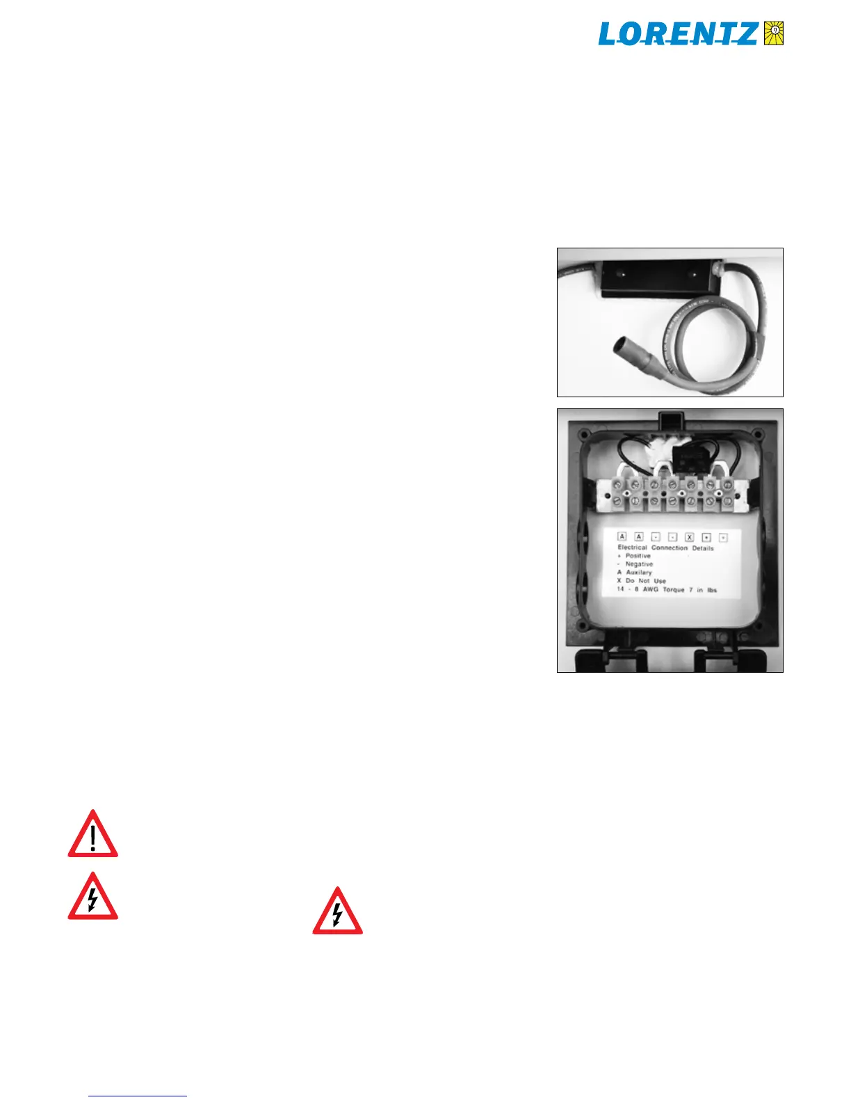
Two types of PV module junction systemsFigure 5:
Quick-connect system using MC connectors (top), junction
box with screw terminals and conduit holes (bottom)

 Loading...


