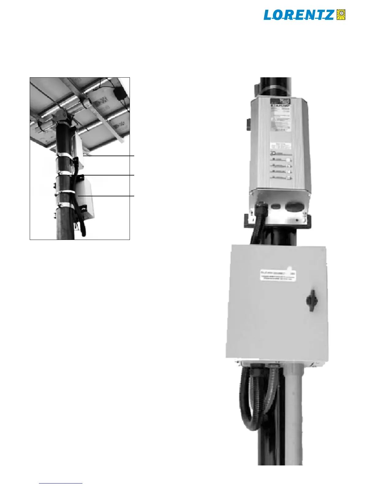
Typical assembly of controller and junc-Figure 3:
tion box on the solar array mounting pole
Boxes are secured using slotted strut and conduit clamps.
Bare ground wires bond the PV modules to the controller
enclosure, and continue down to the ground rod. Flat braid
is flexible and eliminates the need for terminal lugs.
Mount the controller on the north side of the pole to
reduce solar heating.
slotted strut (Unistrut
®
or equivalent),
cut to the width of the box
conduit clamp to fit slotted strut
hose clamp
Conduit holesFigure 4:
3 holes for 3/4 in conduit (28 mm)
1 hole for 1 1/4 in conduit (45 mm)
Holes are in a removable plate that can be reversed.
Rubber plugs are included for unused holes.